STSYSTEMPLC provides an engineering-grade Cold Storage High Bay Light Replacement System for cold warehouses, frozen food logistics and temperature-controlled storage where low temperature, condensation and limited service time make ordinary lamp replacement too expensive or difficult.
The architecture connects Luminaire Terminal, Ground Service Method and Operations Center responsibilities. serviceable high bay LED terminal, locking base, driver interface, sensor point, local tag, selected service device, cabinet control, sensor logic and owner records for cold storage high bay light replacement are packaged as one serviceable lighting system.
Factory Test & Site Commissioning should verify locking behavior, electrical state, service alignment, sensor response, energy records, replacement sequence, failure recovery and owner handover files.
For qualified strategic partners, STSYSTEMPLC can support Partner-Branded Solution Packaging and Owner-Controlled Deployment for Cold Storage High Bay Light Replacement System Projects.
Unmanned high bay light installation fails when the lamp, tool, sensor, cabinet and owner records are treated as separate purchases. STSYSTEMPLC connects the Luminaire Terminal → Ground Service System → Operations Center so cold warehouses, frozen food logistics and temperature-controlled storage can define how LED high bay lights are installed, removed, controlled, verified and handed over.
Video Evidence
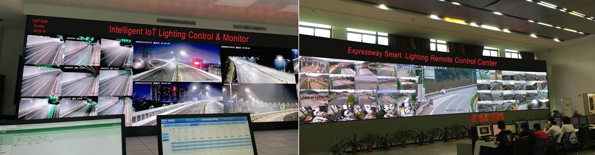
This video is used as top-page field evidence for the unmanned High Bay Light service concept. The final service method, tool boundary, electrical interface and FAT/SAT records remain project-specific.
System Overview
Cold Storage Industrial High Bay Light Replacement System connects LED high bay luminaires, controlled service method, motion or radar sensing, skylight daylight input, cabinet HMI, smart power switching, communication route, service records and owner acceptance documents into one industrial lighting system.
For cold warehouses, frozen food logistics and temperature-controlled storage, the expensive part is often low temperature, condensation and limited service time, not only the lamp. The project must define where the light is installed, how it can be removed, who controls the service method and which record proves completion.
Operational Pain
Scaffolding, aerial vehicles, shutdown windows and safety permits can exceed the visible hardware cost.
A high bay failure may require line stoppage, area isolation, crane coordination or night maintenance.
Unclear service methods create disputes between lighting supplier, installer, electrical team and owner operation team.
A qualified system reduces unnecessary high-altitude work and makes every service action planned, recorded and recoverable.
Lifecycle Risk
8m, 12m, 18m or higher changes tool selection and safety requirements.
Cranes, ducts, racks, machines and platforms may block direct access.
Heat, dust, vibration or humidity changes luminaire and connector decisions.
Uncontrolled replacement creates mixed optics, drivers and dimming behavior.
The owner cannot prove which unit was changed and whether it returned correctly.
Energy and light-level claims cannot be verified without accepted records.
Tender Fit
cold warehouses, frozen food logistics and temperature-controlled storage
Repeated high bay maintenance cost, safety pressure, production interruption or a high-efficiency retrofit plan.
LED high bay terminal, service interface, sensors, cabinet HMI, smart power switch and communication route.
Installation, removal, locking, returned state, sensor response, energy record and handover evidence.
The strongest fit is a site with many high bay lights, difficult access, measurable operating zones and an owner who wants repeatable maintenance control.
Not Every Project
If ordinary ladder access is safe and cheap, a service-system package may be unnecessary.
A few luminaires without service pressure may not justify a full architecture package.
If no one owns records, authority or future maintenance, the system value will be weakened.
Architecture
replaceable high bay LED terminal, locking base, driver interface, sensor point and local tag
ground tool, lift platform, robotic arm or guided service device that installs, removes, lowers and verifies the luminaire from a controlled position.
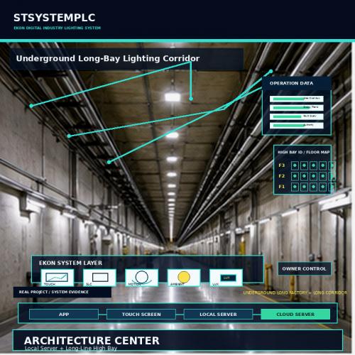
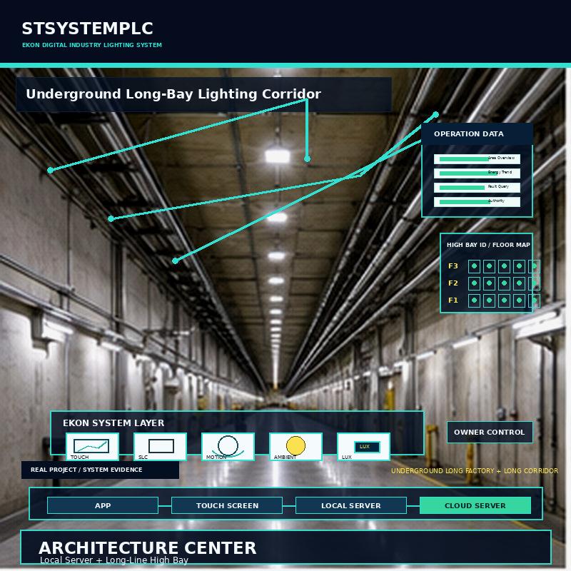
Cabinet HMI, local server, energy record and maintenance workflow give the owner visibility, authority and expansion control.
The three layers are defined together but accepted separately. Terminal tests prove product and interface. Ground service tests prove operation. Operations-center tests prove records, permissions, alarms and handover.
Luminaire Terminal
| Terminal decision | Define before delivery | Verify before handover |
|---|---|---|
| Mechanical interface | Base, locking path, guide feature and engagement rule. | Repeatable installation and removal without structural damage. |
| Electrical interface | Power, driver, dimming, connector, protection and isolation boundary. | Safe state, returned state and correct operation after replacement. |
| Optical output | Beam angle, mounting height, target illuminance and glare control. | Site light-level check or approved photometric evidence. |
| Identity | Model, serial record, zone, address, service date and configuration reference. | Owner record shows what was installed and where. |
Mechanical Service
Useful where alignment and force can be managed from ground level.
Useful when the site can accept equipment movement and floor access.
Useful where repeatability, confined access or safety pressure justifies guided operation.
Useful when the luminaire, ceiling or process needs project-specific tooling.
The tool must match ceiling height, obstruction, weight, locking force, access route, operator skill and emergency release plan.
Installation Workflow
Move the service tool to the approved point and confirm orientation.
Connect the mechanical guide and confirm locking direction.
Complete electrical connection and returned-state check.
Write zone, device identity, operator action and result.
Removal Workflow
Confirm approved power or control state before service.
Use the defined tool path without uncontrolled dropping or twisting.
Bring the luminaire to a safe service position.
Record reason, result, replacement unit and return-to-service check.
Robotic Service
Tool path, force and engagement point are more important than a dramatic robot video.
The operator remains at a controlled position with clear stop and recovery method.
Every action leaves a record that can be compared with later service events.
Electrical Boundary
| Electrical item | Project rule | Acceptance evidence |
|---|---|---|
| Isolation | Define who may isolate or restore the circuit before service. | Visible state and responsible person record. |
| Connector | Define connector type, locking, current, voltage and environmental limits. | Inspection and functional test after installation. |
| Dimming | Define driver interface and control response after replacement. | Command and returned level record. |
| Protection | Keep protection coordination under the responsible electrical team. | Signed boundary and as-built reference. |
Sensor Layer
Detect worker, forklift, vehicle or process movement and raise zone lighting.
Read daylight or skylight contribution and prevent unnecessary high bay output.
Use exterior brightness or weather-related input where the campus condition affects lighting.
Treat sensor unavailable or abnormal value as a verified recovery case.
Skylight Daylight
| Daylight item | Engineering decision | Owner value |
|---|---|---|
| Skylight position | Sensor placement avoids direct glare and reflects useful work-zone brightness. | High bay dimming responds to real daylight contribution. |
| Threshold bands | Daylight, cloudy, dusk and night levels are separated with deadband. | Avoids flicker and unstable dimming. |
| Zone relationship | Roof daylight area is mapped to corresponding high bay circuits. | Energy savings are visible by area. |
Motion Safety
Define whether the target is worker, forklift, crane, vehicle or process movement.
Set hold time and recovery level around actual work behavior.
Avoid leaving active work zones under insufficient lighting after a trigger clears.
Cabinet HMI
Operators select building, zone, service point or lighting group using owner-approved names.
The screen shows installed state, fault status, manual/automatic mode and recent service action.
Only approved users may isolate, override, confirm service or change parameters.
Smart Power Switch
Command and actual circuit state should be visible for selected lighting circuits.
Power behavior should be connected to zone, schedule, sensor and high bay load.
Where approved, switching assists safe maintenance under electrical responsibility rules.
Communication
Useful where power-line communication is practical inside defined cabinet and circuit boundaries.
Useful where wireless reach or field separation makes cabling difficult.
Useful when one industrial site contains different buildings, ceilings, cabinets and obstruction levels.
Local Server
Essential operation and service confirmation at the cabinet or building.
Multi-zone records for mid-size factories or warehouses.
Owner-controlled data, backup and role authority for security-sensitive projects.
Multi-site or campus visibility for long-term management.
Energy Analysis
Energy and lifecycle savings come from high-efficiency LED high bay luminaires, optical design, motion response, skylight daylight harvesting, schedules, dimming levels, smart power records and fewer unnecessary high-altitude service events.
Current production efficiency is built around 200 lm/W-class LED high bay light, while 210–220 lm/W-class options are being advanced for qualified projects. The value is not only the luminaire number. It is the combined result of high-efficiency LED high bay fixtures, motion or radar sensing, skylight daylight harvesting, zone dimming, smart power switching, cabinet-side energy records and owner-verifiable acceptance data.
For Cold Storage Industrial High Bay Light Replacement System, efficiency claims should be confirmed through project-specific photometric output, driver selection, thermal structure, installation height, dimming behavior, operating schedule and FAT/SAT acceptance verification.
Energy lock: if a proposal only offers a service tool or software control while the high bay light load remains low-efficiency, the owner may still pay high access cost on top of an inefficient lighting foundation. STSYSTEMPLC positions the system from the light source to the service record.
Maintenance Records
Model, serial record, zone, position, installation date and configuration reference.
Install, remove, inspect, replace, adjust or return-to-service action with responsible person.
Repeat faults, sensor exceptions, driver issues, connection problems or access difficulties.
Functional test, light response, command state, automatic recovery and owner acceptance.
Safety Boundary
| Safety boundary | Define | Verify |
|---|---|---|
| Access position | Where operators stand, where tools move and which area must be isolated. | Site simulation under representative obstruction. |
| Load handling | Luminaire weight, locking force, lowering method and emergency stop. | Service trial and risk review. |
| Electrical state | Who controls power, dimming and circuit isolation. | Command record and returned state. |
| Production interface | Shutdown window, line clearance, crane or machine coordination. | Owner sign-off and handover file. |
Tooling Decision
Ground service may work when the vertical path is clean and repeatable.
Guided tools or lift-assisted service may be safer around machines and cable trays.
More formal FAT/SAT evidence is required where access mistakes affect safety or production.
The service method should remain usable when more zones or buildings are added.
Spare Strategy
Replacement should not change distribution or target illuminance.
Dimming and control response should remain consistent after replacement.
The owner should trace each spare into the installed record.
Documentation
Lighting and service responsibility by building, floor, line or work area.
Tool, sequence, access condition, operator role and safety boundary.
Luminaire model, identity, interface, optical output and spare route.
Sensor, dimming, manual mode, smart switch and recovery logic.
FAT/SAT result, correction, training and handover confirmation.
Decision Boundaries
| Decision area | Typical high bay light route | STSYSTEMPLC interconnected route |
|---|---|---|
| Starting point | Select fixture, bracket or access contractor first. | Define service risk, access boundary, terminal interface, control record and acceptance method first. |
| Maintenance logic | Treat replacement as manual site work. | Treat installation and removal as a repeatable system workflow. |
| Owner visibility | Lamp list, invoice and occasional failure report. | Zone map, service record, command state, sensor logic, energy trend and closure evidence. |
| Deployment | Separate lighting, access equipment, sensors and dashboard. | Luminaire terminal, ground service method, cabinet HMI, smart power and records integrated by project boundary. |
| Handover | Hardware, manuals and basic operation instruction. | Terminal schedule, service method, FAT/SAT results, training file, authority table and lifecycle record. |
Product Feature Comparison for Owner Review
| Typical Global Platform Strength | STSYSTEMPLC Unmanned High Bay Light Advantage |
|---|---|
| Large SCADA and automation platform | Focused high bay light service layer for unmanned or reduced-height installation, safe removal, high-efficiency LED high bay light and owner-verifiable service records, not a generic plant-wide automation slogan. |
| Enterprise BMS and building automation | Factory, warehouse, aircraft hangar, power plant and production-line lighting maintenance workflow instead of office-building comfort logic. |
| PLC and electrical automation ecosystem | Hybrid PLC + LoRa route for lighting cabinets, service records, motion sensors, skylight daylight inputs and smart power switching. |
| Lighting fixture suppliers | System-level package that connects high-efficiency LED high bay luminaires, service method, sensors, cabinet control and owner handover. |
| Equipment rental and access contractors | Reduced repeated dependence on scaffolding or aerial work vehicles when the site can use ground-side or controlled service tools. |
| Cloud dashboard and remote monitoring | Cabinet-side touchscreen operation, service status, fault history, energy trend and manual recovery remain close to the site. |
| Standard maintenance software | Lighting-specific lifecycle records connect installation, removal, spare consistency, sensor logic, dimming behavior and FAT/SAT results. |
| Large-scale system integration capability | Compact multi-in-one field deployment reduces external boxes, wiring ambiguity, service responsibility gaps and owner training complexity. |
| Vendor-defined platform architecture | Owner-defined authority, data ownership, credential control, acceptance evidence, service record and long-term expansion boundary. |
| Global brand recognition | Infrastructure-proven field engineering discipline and project-specific commissioning records for industrial lighting owners. |
Positioning: STSYSTEMPLC does not claim to replace every SCADA, BMS, PLC, access-equipment or lighting fixture supplier. It locks the high bay light field layer where luminaires, service tools, sensors, touch screens, smart power switches, energy records and owner handover must work together for Cold Storage Industrial High Bay Light Replacement System.
The comparison is not about company size. It asks which route reduces hidden access cost, safety ambiguity, service downtime and long-term owner dependence.
Compatibility
Keep existing luminaires only when electrical, mechanical, optical and control requirements are compatible.
Use interface modules, cabinet changes or sensor mapping where the risk is controlled.
Replace where efficiency, safety, dimming or service interface cannot meet the accepted system duty.
Factory Preparation
Engage, lock, release and lower under the approved tool method.
Power, dimming, returned state and safe recovery after replacement.
Motion, ambient or weather input reaches the correct lighting zone.
Service event, device identity and acceptance result can be stored and exported.
Failure Verification
Confirm the service method prevents unsafe locking or uncontrolled release.
Confirm identity mismatch is visible before owner acceptance.
Confirm safe state, returned circuit status and recovery record.
Confirm fallback level and alarm display follow the approved logic.
Confirm local lighting and service records remain usable as defined.
Confirm authority, confirmation and training reduce incorrect commands.
Recovery Logic
Identify luminaire, zone, circuit, sensor or tool exception.
Replace, adjust, reconfigure or isolate according to the approved boundary.
Check light output, command response, sensor logic and energy record.
Record responsible person, result, remaining issue and owner acceptance.
Training
Approves timing, area access and production coordination.
Executes service method, replacement, inspection and closeout.
Controls circuit boundary, isolation and compliance responsibility.
Manages users, records, backups, permissions and expansion baseline.
Scalable Series
Ground service method plus cabinet HMI and simple service record.
Multi-zone HMI, sensor logic, selected smart power switching and local server.
Private server, operations-center dashboard, authority table and batch service plan.
Partner-branded templates, drawings, acceptance files and long-term delivery package.
Partner Packaging
Clarify site pain, access cost, safety risk, efficiency target and evidence plan.
Support topology, tool method, high bay efficiency, sensors, cabinet control and FAT/SAT response.
Support configuration records, site commissioning, training, handover and maintenance baseline.
Infrastructure Proven
Infrastructure-scale field experience is used here as engineering discipline: naming, mapping, commissioning, records, recovery and owner handover.
Procurement Lock
200 lm/W-class production baseline with advanced options under verification.
Ground-side, robotic or controlled service route where site conditions support it.
Cabinet HMI, sensor priority, zone dimming and smart switching.
Installation, removal, fault, recovery, energy and handover evidence.
User roles, data ownership, backups and service boundary.
Factory Test & Site Commissioning
| Acceptance group | Representative verification | Required evidence |
|---|---|---|
| Terminal identity | Luminaire model, interface, lock, driver, dimming and zone mapping. | Signed terminal schedule and screen/record evidence. |
| Service method | Install, remove, lower, replace and return using approved tool route. | Test sequence with expected and actual state. |
| Control logic | Manual mode, sensor trigger, dimming, smart switch and recovery priority. | Command, returned state and alarm record. |
| Energy baseline | 200 lm/W-class luminaire, schedule, dimming and selected metering fields. | Photometric or project record and energy sample. |
| Owner authority | Users see and perform only approved service and control actions. | Role matrix and audit record. |
Site commissioning must use real ceiling height, obstruction, route, daylight, movement and operator behavior.
Handover Package
Zone map, mounting points, device identities, cabinet routes and communication reference.
Tool method, safety steps, replacement sequence, spare list and training record.
Schedules, sensor thresholds, dimming levels, authority table and fallback logic.
FAT/SAT results, deviations, corrective actions, open-item closure and sign-off.
Related High Bay Light System Pages
FAQ
No. The system connects luminaire terminal, service method, cabinet control, sensors, smart power records and owner handover.
Yes. Current production positioning is built around 200 lm/W-class high bay light, with 210–220 lm/W-class options being advanced for qualified projects after verification.
No. Ceiling height, obstruction, luminaire weight, access route, electrical boundary and safety policy must be checked first.
Yes. Motion or radar sensing, skylight daylight input and weather-related brightness data can be integrated when zones, thresholds, delays and fallback logic are defined.
Yes. The architecture can use cabinet HMI, local server, private server or operations-center deployment according to owner policy.
Send ceiling height, luminaire quantity, mounting interface, access restriction, production schedule, sensor requirements, existing circuit condition, preferred service method and owner handover requirement for an engineering review.

Address : F4,Bldg A, Hanzhong Industrial Park, No.67, North of Xinsha Ave, Xin Tang, Zeng Cheng, Guang Zhou, China
Tel : +86 20 8278 0427
Email : info@stsystemplc.com
Email : morrison426@163.com