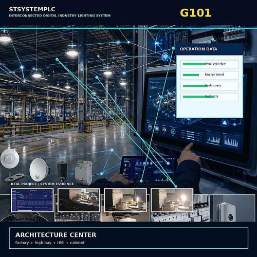
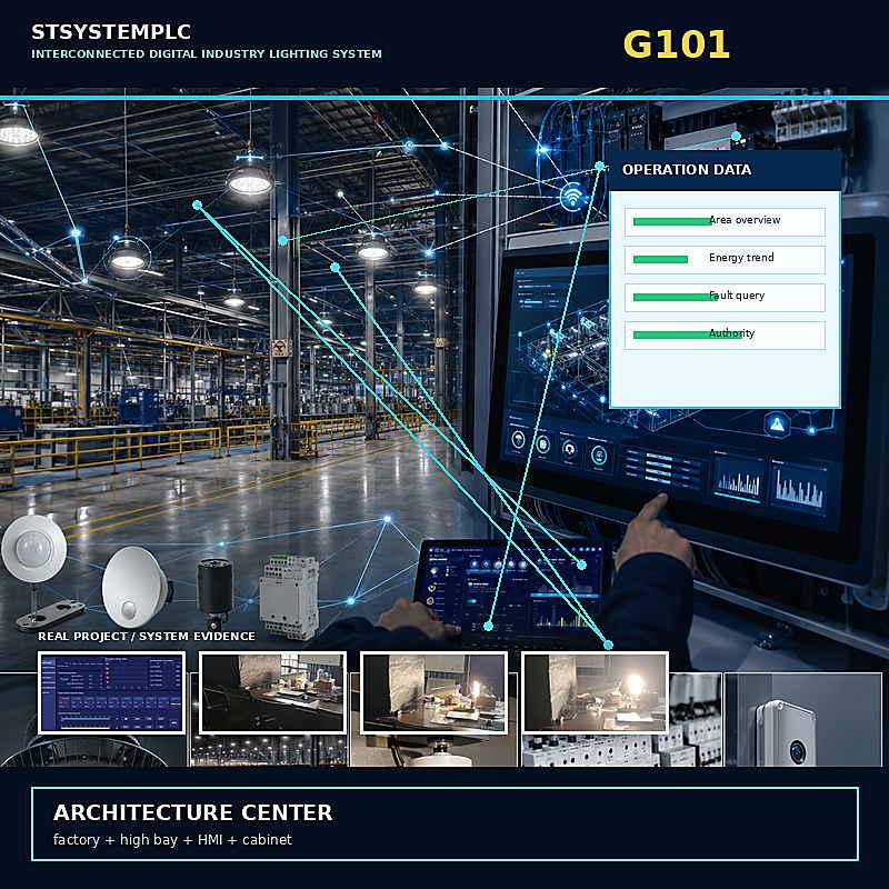
STSYSTEMPLC provides an engineering-grade Interconnected Digital Industry Lighting System for factories, warehouses, power plants and high-ceiling facilities that need lighting zones, sensor response, local operation and maintenance records to work as one owner-controlled system.
The architecture connects Lighting Terminal, Control System and Operations Center responsibilities. High bay luminaires, motion or radar sensing, ambient-light inputs, schedules, local HMI, PLC, LoRa, RS485 and private-server routes can be selected around the site rather than forced into a single device-only package.
Factory Test & Site Commissioning should verify zone names, device IDs, sensor-to-light response, manual and automatic recovery, communication loss behavior, alarm records, operator permissions and owner handover files.
For qualified strategic partners, STSYSTEMPLC can support Partner-Branded Solution Packaging and Owner-Controlled Deployment for Security-Sensitive Infrastructure Projects.
Industrial lighting fails as a system when zones, sensors, overrides, communications and owner records remain disconnected. STSYSTEMPLC connects the Lighting Terminal → Control System → Operations Center so factories, warehouses, power plants and high-ceiling facilities can define how light responds, who controls it, how failures recover and what evidence is handed to the owner.
System Overview
Interconnected Digital Industry Lighting System connects high bay luminaires, industrial lighting zones, motion or radar sensing and ambient-light inputs, zone schedules, trigger priorities, manual override recovery and local HMI records, local operator control, communication routes and owner-side records into one project-defined operating system. It is designed for factories, warehouses, power plants and high-ceiling facilities where lighting must respond to real work conditions while remaining visible, testable and transferable to the owner.
The system is not defined by a single lamp, controller or dashboard. It begins with the operating rule for every relevant area: what triggers light, what level is required, who may override it, what happens after communication loss and which record proves the result.
Once those rules are fixed, the terminal, control and operations layers can be selected without turning the project into a collection of disconnected devices. This is the difference between buying smart-looking products and building an industrial lighting system that can be commissioned, operated and expanded.
Operational Pain
Operators cannot see which area, schedule, sensor or circuit owns each lighting action.
Manual commands solve a temporary problem, then remain active without a defined return to automatic mode.
Faults are discovered during inspection or production complaints because status and alarms are not organized.
The owner receives hardware and a login, but not a verified zone map, authority matrix, trigger table or recovery record.
For factories, warehouses, power plants and high-ceiling facilities, the visible lamp is only the endpoint. The real risk is spread across mounting height, circuit access, sensor coverage, shifts, access restrictions, maintenance windows and production safety. A fragmented design transfers this complexity to the owner after commissioning.
Tender Fit
factories, warehouses, power plants and high-ceiling facilities.
lighting zones, sensor response, local operation and maintenance records to work as one owner-controlled system.
high bay luminaires, industrial lighting zones, motion or radar sensing and ambient-light inputs.
zone schedules, trigger priorities, manual override recovery and local HMI records.
The strongest fit is a project with many luminaires, multiple operating zones, measurable sensor or schedule logic, local control requirements and an owner who expects acceptance evidence. Retrofit projects are also suitable when existing luminaires, circuits or cabinets can be mapped into an approved control boundary.
Lighting Terminal → Control System → Operations Center
High bay luminaires, dimming devices, motion or radar sensors, illuminance inputs, circuit switches and selected metering points execute and report field actions.
Zone logic, schedules, trigger priorities, manual/automatic state, communication handling and alarm rules convert field devices into a coordinated system.
Local HMI, server, dashboard and approved interfaces give the owner visibility, authority, history, maintenance workflow and expansion control.
The three layers are defined together but accepted separately. Terminal tests prove device response. System tests prove logic, priority and recovery. Operations-center tests prove visibility, permissions, records and owner handover. This prevents a dashboard screenshot from being treated as proof that the field system works.
Terminal Layer
| Terminal group | Project decision | Acceptance evidence |
|---|---|---|
| High bay luminaire | Power, light distribution, dimming interface, mounting height, thermal environment and service method. | Model record, address or zone mapping, command response and approved light level. |
| Motion or radar input | Detection area, target type, mounting position, delay time, false-trigger risk and recovery rule. | Walk, vehicle or process simulation with time-stamped zone response. |
| Ambient-light input | Measurement position, shielding, useful range, threshold bands, deadband and sampling rule. | Reference comparison, threshold test and stable return behavior. |
| Circuit switch or meter | Load type, current range, cabinet space, protection boundary, switching authority and data fields. | Circuit label, returned state, alarm record and meter-field verification. |
Terminal selection is completed only after the operating duty is clear. A sensor range printed in a brochure does not prove coverage in a steel structure, high rack aisle or dusty workshop. The project must convert device capability into a placement and acceptance plan.
Control System Layer
Industrial lighting may receive commands from schedules, daylight thresholds, motion or radar triggers, local HMI, authorized remote users, maintenance mode and emergency or safe-state rules. Without a priority table, two valid functions can create an invalid operating result.
Schedule and sensor logic operate within approved zone limits, dimming levels and delay times.
An operator temporarily overrides automatic behavior with visible status, permission and a defined release method.
The system returns from override, restart or communication loss to an approved state without leaving zones in an unknown condition.
The final priority table should state which command wins, how long it remains active, what the HMI displays and how the system returns. This table becomes a FAT and site-commissioning instrument, not merely a programming note.
Operations Center Layer
Building, floor, workshop, aisle and zone status using the same names as drawings and acceptance records.
Online state, lighting level, manual/automatic state, current command source and communication condition.
Fault, recovery, operator action, device change and maintenance acknowledgement with time and identity.
Selected circuit or zone records compared by approved period, baseline and operating context.
The operations center may be a local touch screen, small local server, private server or customer platform interface. The correct level depends on site size, network policy, owner capability and long-term operations—not on how impressive the first demonstration looks.
Zone Engineering
Good zoning follows operational responsibility. A factory may require zones by production line, crane span, inspection station, maintenance corridor, storage aisle, loading dock or emergency access. A warehouse may require different rules for picking aisles, cross aisles, staging areas and high-traffic loading zones.
| Zone record | Minimum definition | Why the owner needs it |
|---|---|---|
| Identity | Unique zone name, building/floor reference and drawing position. | Prevents operators, software and electricians from using different names. |
| Lighting duty | Normal, reduced, standby and maintenance levels where applicable. | Connects control behavior to the actual work performed in the area. |
| Trigger source | Schedule, sensor, local command, approved remote command or linked process. | Explains why the zone changed and which priority applies. |
| Recovery rule | Delay, deadband, return level, restart state and exception handling. | Prevents a temporary event from creating a permanent operating change. |
Local HMI
Operators choose an approved building, workshop or zone without searching through raw device IDs.
The interface distinguishes commanded level, returned state, communication status and manual/automatic mode.
Only authorized actions are exposed, with confirmation where required and a clear path back to automatic operation.
The HMI should support the people who work at the facility: shift supervisors, maintenance technicians, energy teams and authorized administrators. Their permissions and tasks are different. The screen structure should reflect those responsibilities instead of giving every user the same powerful controls.
Device debugging functions may read identity, version, status or approved parameters, but technician-level tools should remain separated from normal operator screens.
Manual / Automatic Control
Record operator identity, selected zone, requested level, issue time, reason where required and whether the command expires automatically or requires authorized release.
Confirm the system returns to the approved schedule and sensor logic, displays the recovered mode and does not retain an obsolete command after restart.
Maintenance, inspection and production changes make manual operation necessary. The engineering objective is not to prohibit override; it is to prevent invisible override. The owner should always be able to see which zones are outside automatic operation and how they return.
Schedule Management
A single daily timetable rarely fits an industrial site. Production areas may use shift calendars, logistics zones may follow vehicle activity, maintenance areas may use task-based windows and outdoor yard lighting may use sunrise/sunset logic. Holidays, shutdowns and special production periods require controlled exceptions.
Every later period must follow the approved time sequence so invalid schedules are detected before release.
The schedule applies to named areas, not an unverified list of device addresses.
Dimming or CCT mode is selected only where the configured equipment supports it.
Commissioning verifies the schedule stored for the area, not only the value sent from the interface.
Ambient-Light Logic
Ambient-light control should reduce unnecessary output without making the site visually unstable. Sensor placement, shielding, reflected light, skylight geometry, weather variation, dust and luminaire feedback can all affect the reading. The control logic therefore needs threshold bands, deadband, sampling behavior and delay rules.
| Design question | Engineering response | Site test |
|---|---|---|
| Where is useful daylight present? | Map windows, skylights, doors and changing sun paths by zone. | Compare representative bright, overcast and low-light conditions. |
| Can the sensor see the controlled luminaires? | Avoid feedback positions that make the system chase its own output. | Change the lighting level and confirm stable sensor behavior. |
| How quickly should lighting change? | Use delay and deadband appropriate to the work area and visual duty. | Cross thresholds repeatedly and confirm no rapid oscillation. |
| What happens if the reading is invalid? | Apply a defined fallback level and alarm or maintenance response. | Disconnect or simulate an invalid input during commissioning. |
Motion & Radar Logic
Worker motion, forklifts, cranes, conveyor activity and vehicles have different speed, direction and coverage requirements. A short-range motion sensor may fit enclosed work areas, while a radar route may be evaluated for longer approaches or moving targets. Every selected device must be proven in the actual mounting and obstruction conditions.
Define people, forklift, vehicle, machine movement or a combination.
Define the useful detection area, blind zones, overlap and interference boundary.
Define target zone, light level, response expectation and any linked adjacent zone.
Define hold time, staged reduction, standby level and return to schedule.
Reference ranges such as approximately 0–10 m for selected motion scenarios or longer radar coverage up to a project-defined limit are equipment-dependent. They belong in the device schedule and site test plan, not as universal system claims.
Trigger Matrix
| Input condition | Decision logic | Lighting response | Return condition |
|---|---|---|---|
| Shift start | Approved calendar and active production zone. | Move selected zones to operating level. | Shift end, authorized exception or sensor-based reduction. |
| Worker or vehicle detected | Qualified target inside mapped area; priority checked. | Raise target zone and approved approach zone. | Delay expires without a new qualified event. |
| Useful daylight increases | Reading remains above threshold for the approved period. | Reduce daylight-responsive luminaires within minimum duty. | Reading crosses lower threshold after deadband and delay. |
| Manual maintenance command | Authorized operator, named zone and visible manual mode. | Set the maintenance level or scene. | Authorized release, expiry or approved automatic recovery. |
| Sensor or communication fault | Invalid or missing data reaches the configured timeout. | Apply the approved fallback state and create an exception record. | Valid data returns and the recovery condition is satisfied. |
Fail-Safe Operation
Industrial operations continue through server maintenance, network interruption and temporary device faults. The project should define which functions remain local, which schedules or thresholds are stored at the field or control layer and which remote functions may pause without affecting minimum lighting duty.
Selected zones continue under their approved local schedule, sensor or fallback rule; the owner sees the exception after the route recovers.
The system returns to an approved state and does not unknowingly restore a stale temporary override.
The affected zone uses its defined fallback level while the fault is displayed and assigned for maintenance.
The correct fallback is project-specific. A warehouse aisle, inspection point, crane area and unmanned storage bay may require different minimum behavior. These decisions belong in the zone schedule and acceptance matrix.
Sensor Placement
Sensor quantity cannot be selected from floor area alone. Ceiling height, rack geometry, steel structures, cranes, walls, dust, heat sources, doors and vehicle direction change the useful detection or measurement area. Each sensor should have an installation position, coverage purpose and linked zone.
Record operating routes, obstructions, daylight openings, ceiling structure and existing cable paths.
Place tentative coverage on the zone drawing and identify blind or overlapping areas.
Use representative workers, vehicles and environmental conditions at the intended mounting height.
Approve position, zone link, thresholds, delays and test result in the handover package.
Field Communications
| Route | Where it helps | What must be verified |
|---|---|---|
| PLC | Uses the power-line route where dedicated communication wiring is difficult and circuit conditions are suitable. | Distribution boundary, attenuation, noise, branch topology, repeater need and recovery. |
| LoRa | Supports wireless field communication where radio coverage and installation policy allow it. | Gateway position, metal obstruction, interference, link margin, antenna and fallback. |
| RS485 | Connects local devices and sensors through an industrial wired bus. | Cable type, segment length, topology, termination, addressing and surge/noise environment. |
| Ethernet / Cellular Backhaul | Connects local systems, servers or approved remote operation routes. | Network ownership, security policy, bandwidth, availability and command authority. |
Hybrid PLC + LoRa may be evaluated where one field route cannot serve every area reliably. Hybrid means engineered diversity, not uncontrolled duplication. Device mapping and command ownership must remain clear.
Retrofit Path
Keep suitable luminaires, dimming interfaces, circuits or cabinets after compatibility and condition verification.
Add approved control terminals, gateways, sensors or local HMI where they create measurable operational value.
Replace incompatible or unreliable components whose limitations would prevent testing, recovery or long-term support.
The retrofit survey should record base or driver interface, circuit grouping, spare cabinet space, wiring route, local switching, existing controls, mounting access and service responsibility. The proposal must state what is retained, what is modified and who accepts each interface.
A retrofit that hides old uncertainty behind a new dashboard is not an upgrade. The owner should receive a clearer system boundary after the work than before it.
Local Operation
Factories and power facilities may restrict internet access, remote commands or cloud dependence. The architecture can place schedules, sensor response, local HMI and selected records inside the site, then add private-server or approved remote access only where the owner requires it.
Selected local control continues under the approved rule when the upper-layer connection is unavailable.
Authorized operators view areas, states, alarms and controls within the facility.
The owner retains system records and management functions inside its controlled environment.
Selected data or commands connect to an owner platform under a defined interface and authority boundary.
Deployment Series
| Deployment level | Typical owner need | System boundary |
|---|---|---|
| Lightweight local operation | One small site needing zone control, schedules and basic status without a large server. | Field control plus local interface; records and access matched to the site. |
| Local small server | One factory or warehouse requiring history, permissions, alarms and maintenance records. | Site-owned server and local network with defined backup and administrator responsibility. |
| Private enterprise server | Multiple buildings or sites requiring centralized policy and owner-controlled data. | Field systems remain site-resilient while approved information reaches the enterprise layer. |
| Operations center | Large industrial groups or high-value infrastructure requiring multi-site decisions and service workflow. | Unified naming, permissions, reporting and integration across independently accepted sites. |
Authority Management
| Role | Typical visibility | Typical authority | Required record |
|---|---|---|---|
| Operator | Assigned areas, current mode, alarms and permitted controls. | Approved zone actions and acknowledgement within shift duty. | User, time, zone, action and returned state. |
| Maintenance | Device identity, fault history, communication and diagnostic fields. | Maintenance mode and approved service commands. | Fault, action, replaced component, result and release. |
| Energy / Facility Manager | Trends, schedules, zone comparison and selected energy records. | Policy review and approved schedule adjustment. | Old value, new value, approver and effective time. |
| Administrator | System configuration, users, interfaces and audit history. | Controlled configuration and authority management. | Configuration version, administrator and change reason. |
Password confirmation or equivalent authorization may be required for control-related commands according to the selected system and owner policy. The handover package must identify who creates, changes and revokes users.
Owner Data Boundary
Zone state, command source, sensor condition, alarm, recovery and maintenance records.
Device schedule, addresses, configuration, drawings, trigger matrix and acceptance results.
User roles, permissions, change history, backups and interface credentials managed under owner policy.
The proposal should state where each data class is stored, how long it is retained, who may export it, how backups are handled and what is delivered at handover. A local server does not automatically create owner control; the operational and administrative responsibilities must also be transferred.
Fault Workflow
Identify the available device, lamp, circuit, sensor, controller or communication exception.
Present the approved site, building, area, zone and device identity.
Route the event to the responsible operator, technician or integrator boundary.
Record action, replacement, restored state, verification and closure time.
Alarm quantity is not a performance metric by itself. The owner needs useful severity, clear location, controlled acknowledgement and a record showing whether the operating condition recovered. Repeated communication events should be analyzed as a route or environment problem, not closed as isolated screen notifications.
Maintenance Records
Model, address, zone, location, installation date and configuration reference.
Observed condition, detection source, operating impact and repeat pattern.
Inspection, adjustment, replacement, firmware or configuration action with responsible person.
Functional test, zone response, automatic recovery and approved closure.
High-ceiling maintenance is costly because access, production coordination and safety control often exceed the cost of the component itself. Accurate records allow teams to combine work, identify repeat failures and prepare the correct device or access equipment before entering the area.
Energy Analysis
Energy results depend on operating hours, production activity, daylight, occupancy, target lighting level, luminaire power and the control strategy. The system should preserve enough context to compare like with like. A monthly power number without zone, schedule and operating condition cannot explain performance.
| Record | Use | Boundary |
|---|---|---|
| Zone operating hours | Compare how long zones remain at operating, reduced or standby levels. | Requires reliable state or command history. |
| Selected circuit energy | Compare approved periods and identify abnormal load behavior. | Metering scope and accuracy depend on selected terminal equipment. |
| Sensor events | Explain why a zone increased or reduced lighting output. | Event count must be interpreted with delay and recovery logic. |
| Production context | Distinguish true control improvement from lower site activity. | Usually supplied or approved by the owner. |
Current production efficiency is built around 200 lm/W-class LED high bay lighting, while 210–220 lm/W-class options are being advanced for qualified projects. The value is not only the luminaire number. It is the combined result of high-efficiency LED high bay fixtures, motion or radar sensing, skylight daylight harvesting, zone dimming, smart power switching, cabinet-side energy records and owner-verifiable acceptance data.
For Interconnected Digital Industry Lighting System, efficiency claims should be confirmed through project-specific photometric output, driver selection, thermal structure, installation height, dimming behavior, operating schedule and FAT/SAT acceptance verification.
Energy lock: if a proposal only offers software control while the high bay lighting load remains low-efficiency, the owner may receive an expensive dashboard attached to an inefficient lighting foundation. STSYSTEMPLC positions the system from the light source to the cabinet record.
Optional Smart Power Layer
Smart power switching or metering can be added for selected lighting circuits when the owner needs cabinet-level visibility, returned switching state, energy records or integration with a broader field power strategy. It should follow the lighting architecture, not replace it.
Remote circuit isolation under approved authority, branch status, selected measurement and alarm linkage.
Load type, current range, protection coordination, cabinet space, wiring and electrical responsibility.
Command permission, returned state, meter fields, alarm flow, local override and safe recovery.
A smart power device must never be treated as a generic substitute for the electrical design. The responsible electrical team retains protection and compliance authority according to the project.
Existing Platform Integration
| Integration item | Define before development | Verify before handover |
|---|---|---|
| Data points | Names, units, source, update behavior, quality and ownership. | Mapped values match approved field and HMI records. |
| Commands | Permitted targets, user authority, confirmation, priority and returned state. | Authorized command reaches the correct zone and recovery is recorded. |
| Alarms | Severity, identity, time source, acknowledgement and closure responsibility. | Simulated faults appear, recover and close under the approved workflow. |
| Network boundary | Protocol, gateway, firewall, addressing, security policy and support responsibility. | Connection remains stable and failures are localized to the agreed boundary. |
Integration is complete when both sides accept the point list, command rules, test method and long-term support boundary. A protocol name alone is not an integration design.
Decision Boundaries
| Decision area | Typical device-centered route | STSYSTEMPLC interconnected route |
|---|---|---|
| Starting point | Controller, lamp, sensor or dashboard selected first. | Operating zones, control responsibility, recovery and acceptance defined first. |
| Field logic | Multiple device functions configured separately. | Schedule, sensor, override and fallback resolved in one approved priority matrix. |
| Owner visibility | Product status pages and isolated alarms. | Area-based operation, command source, faults, history and maintenance workflow. |
| Deployment | Cloud or platform route determined by the product family. | Local HMI, small server, private server or operations center selected by owner policy. |
| Handover | Hardware list, manuals and software access. | Zone map, trigger matrix, authority table, FAT/SAT results, records and service boundary. |
Product Feature Comparison for Owner Review
| Typical Global Platform Strength | STSYSTEMPLC Interconnected Digital Industry Lighting Advantage |
|---|---|
| Large SCADA and automation platform | Focused industrial lighting control layer for industrial high bay lighting zones, sensors, cabinet control, energy records and owner handover evidence, not a generic plant-wide automation slogan. |
| Enterprise BMS and building automation | Factory, warehouse, power plant, aircraft hangar and production-line lighting workflow instead of office-building comfort logic. |
| PLC and electrical automation ecosystem | Hybrid PLC + LoRa route for lighting cabinets, field controllers, motion sensors, daylight sensors and smart power switching. |
| Network-centered infrastructure platform | Owner-controlled local HMI, small server, private server or operations-center deployment without forcing one network platform. |
| Cloud dashboard and remote monitoring | Cabinet-side touchscreen operation, zone dimming, alarm records, energy trend and manual override remain close to the site. |
| Standard energy monitoring software | Lighting-specific energy analysis connects lux input, skylight daylight harvesting, motion-trigger logic and high bay power behavior. |
| Lighting fixture and sensor suppliers | System-level coordination of LED high bay lights, ambient sensors, weather sensors, motion/radar sensors and smart power switches. |
| Large-scale system integration capability | Compact multi-in-one field deployment reduces external boxes, wiring ambiguity and commissioning responsibility gaps. |
| Vendor-defined platform architecture | Owner-defined authority, data ownership, credential control, FAT/SAT records, point-list files and long-term service boundary. |
| Global brand recognition | Infrastructure-proven field engineering evidence and project-specific commissioning discipline for industrial lighting owners. |
Positioning: STSYSTEMPLC does not claim to replace every SCADA, BMS, PLC or network platform. It locks the industrial lighting field layer where high bay lights, sensors, touch screens, smart power switches, energy records and owner handover must work together for Interconnected Digital Industry Lighting System.
The comparison is not about company size or brand recognition. It asks which route gives the owner a clearer field boundary, lower commissioning ambiguity and greater long-term control for the actual industrial site.
Factory Test Scope
| FAT group | Representative verification | Required evidence |
|---|---|---|
| Identity and mapping | Devices, zones, groups, sensor inputs and interface points match the approved schedule. | Signed mapping sheet and screen/record evidence. |
| Control priority | Schedule, sensor, manual command, maintenance mode and fallback interact correctly. | Test sequence with expected and actual state. |
| Alarm and recovery | Selected device, sensor or communication faults create the correct display and recovery record. | Alarm identity, time, acknowledgement and closure. |
| Authority | Users can see and perform only the functions approved for their roles. | Role matrix and command audit record. |
| Data and export | Selected status, trend, energy or maintenance fields are stored and exported as defined. | Sample record and owner review. |
Site Commissioning Scope
Site commissioning verifies conditions that a factory simulation cannot reproduce: actual mounting height, steel obstruction, rack geometry, cable routing, power noise, radio coverage, daylight, moving targets, production schedules and operator behavior.
Model, position, address, zone, wiring, cabinet and label match approved drawings.
Representative worker, forklift, vehicle, daylight and command tests reach the correct lighting zones.
Communication, sensor, controller restart and selected device exceptions follow the approved fallback.
Authorized personnel perform normal tasks, acknowledge alarms and return overrides to automatic mode.
Acceptance Matrix
| Requirement | Factory proof | Site proof | Handover record |
|---|---|---|---|
| Zone control | Mapped command and returned state. | Correct installed area responds. | Zone schedule and signed result. |
| Sensor logic | Simulated input, priority, delay and recovery. | Real target or ambient condition test. | Trigger matrix and coverage record. |
| Manual/automatic mode | Role, command, visible state and release. | Authorized operator completes the workflow. | Authority table and operation instruction. |
| Communication loss | Configured timeout, fallback and recovery. | Representative field route interruption. | Failure test and recovery record. |
| Alarm workflow | Fault identity, severity, acknowledgement and closure. | Selected installed exception test. | Alarm list and maintenance responsibility. |
| Owner data | Storage, history, export and backup sample. | Owner environment and access check. | Data boundary, backup and administrator file. |
Failure Verification
Confirm the zone enters its approved fallback and the system identifies the affected input.
Confirm local operating duty, visible exception, timeout and recovery after the route returns.
Confirm startup state, retained configuration and return to the correct mode.
Confirm the action is blocked or controlled and the event is recorded according to policy.
Confirm commissioning detects the mismatch before the owner signs the area result.
Confirm essential local lighting rules continue and records reconcile as designed.
Failure verification is where an interconnected system proves its value. Normal demonstration shows what happens when everything is available; engineering acceptance shows what the owner can expect when something is not.
Handover Package
Zone drawings, device and address schedules, cabinet and network routes, interface list and configuration reference.
Schedules, trigger matrix, priorities, manual/automatic recovery, fallback and alarm workflow.
FAT and site results, deviations, corrective actions, open-item closure and owner sign-off.
User roles, training, backups, maintenance records, spare strategy and long-term service boundary.
The handover package becomes the baseline for later expansion. New zones, sensors, buildings or operations-center functions should reference the accepted naming and responsibility structure rather than creating a second system beside the first.
Infrastructure Proven
Infrastructure-scale field experience is used here only as a background engineering reference. The visible proposal stays focused on factories, warehouses, power plants and high-ceiling facilities, lighting zones, sensor response, local operation and maintenance records to work as one owner-controlled system, control authority and handover evidence.
Engineering Reference
For this industrial lighting matrix, embedded video is not the main persuasion device. If the owner needs visual evidence, it should be treated as a light reference for STSYSTEMPLC field discipline, while the page itself must win through architecture, sensor logic, commissioning records and owner-controlled deployment.
Control room operation, terminal mapping, zone switching, sensor response, HMI records and field acceptance evidence.
Overusing unrelated transport-infrastructure footage on an industrial lighting page, because it shifts attention away from the factory problem.
Any external field reference must still be converted into this project's topology, device limits, FAT/SAT results and signed handover files.
Procurement Lock
Where lighting responsibility begins and ends.
Why each zone changes and how it returns.
Who may see, command, configure and approve.
How every critical function is proven.
What the owner receives for long-term control.
If a supplier cannot develop these five documents, the owner is being asked to accept hidden integration and operating risk. Equipment specifications remain necessary, but they do not replace the system definition.
Strategic Partner Support
For qualified strategic partners, STSYSTEMPLC can support partner-branded solution packaging, architecture diagrams, zone and trigger templates, device schedules, FAT/SAT checklists, owner-facing technical explanations and project-specific deployment routes.
Clarify owner pain points, project fit, architecture boundary, differentiation and evidence plan.
Support topology, communication, sensor logic, server route, interface, responsibility and acceptance responses.
Support configuration records, factory tests, site commissioning, training and owner handover documentation.
Owner-controlled deployment can be prepared for government, energy, industrial and security-sensitive projects using on-premise servers, local command-center operation or closed-network environments according to project requirements and owner policy.
Engineering FAQ
Yes, when the existing power, driver or dimming interface, circuit grouping, installation condition and control method are compatible with the approved retrofit architecture. The survey must identify which components are retained, adapted or replaced.
Yes. The architecture can keep selected schedules, sensor logic, local HMI and fallback behavior at the site. The exact autonomous scope, record handling and recovery route must be defined for the project.
Yes, when every input has a mapped zone, priority, threshold or qualification rule, delay, recovery and failure response. The site test must prove the combined behavior under representative conditions.
The project defines an authorized release, expiry or recovery rule. The system should display manual state and record the transition back to the approved automatic logic.
Selected data and commands can be integrated through a project-defined interface. Point list, protocol, command authority, returned state, alarm workflow, network boundary and acceptance method must be agreed.
As-built drawings, device and zone schedules, trigger and authority matrices, configuration references, FAT/SAT results, user and backup records, training materials, maintenance workflow and the agreed service boundary.
Send the building use, lighting schedule, ceiling height, operating zones, sensor requirements, existing circuit and communication conditions, local-server preference, owner authority and required handover records for an engineering review.

Address : F4,Bldg A, Hanzhong Industrial Park, No.67, North of Xinsha Ave, Xin Tang, Zeng Cheng, Guang Zhou, China
Tel : +86 20 8278 0427
Email : info@stsystemplc.com
Email : morrison426@163.com