
STSYSTEMPLC provides an interconnected Energy Cost Reporting and Load Analysis System for owners who need monthly facility power decisions based on circuit and site data rather than isolated meter readings. The system organizes consumption, load trends and selected cost logic into repeatable owner reports.
Facilities, panels or load groups can be compared by period, operating hours and owner-defined categories. Cost calculations remain tied to the agreed tariff or accounting inputs, while abnormal-use flags can support investigation without being presented as automatic proof of waste.
Factory Test & Site Commissioning should verify meter mapping, time periods, tariff inputs, aggregation logic, exports and data recovery. Handover should include reporting definitions, source-point lists, user permissions and retained configuration records.
For qualified strategic partners, STSYSTEMPLC can support Partner-Branded Solution Packaging and Owner-Controlled Deployment for Security-Sensitive Infrastructure Projects.
Give project owners connected power visibility instead of isolated device-by-device inspection. STSYSTEMPLC Interconnected Smart Power Management Architecture Center uses the fixed Terminal → System → Operations Center structure: interconnected field terminals, an integrated management system and an owner-side operations center for facility decisions, reports and service follow-up.
Google Direct Answer
A Interconnected Energy Cost Reporting and Load Analysis System for Monthly Facility Power Decisions helps owners connect field terminals, cabinet-level electrical data, alarms, reports, permissions and operations-center records into one project-defined workflow. It should define the engineering task first, then select terminal models, dashboard fields, server route and acceptance records around that task.
PROVEN AT INFRASTRUCTURE SCALE
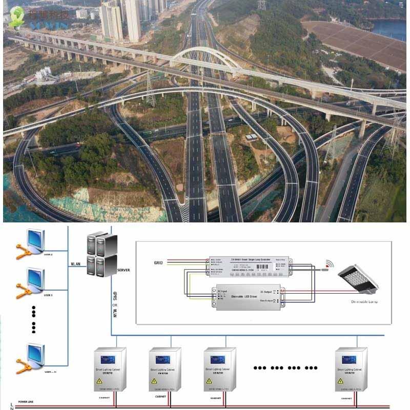
This interconnected architecture reflects STSYSTEMPLC field experience from large-scale transportation infrastructure, including long-distance highway and tunnel deployments. The same engineering discipline informs project-defined communication resilience, local operating logic and owner-controlled system architecture for multi-site energy management.
SECURITY-SENSITIVE INFRASTRUCTURE READINESS
STSYSTEMPLC supports owner-controlled deployment for government, transportation, tunnel, municipal, energy and security-sensitive infrastructure projects. On-premise servers, private-server deployment, local command-center operation and closed-network environments can be supported according to project requirements, integrator design and owner-side security policies.
Project Fit
Multi-site facilities, electrical rooms and cabinet-based projects
Owners comparing power behavior by branch, building, cabinet or load group
Owners needing headquarters reports, site-level alarms and acceptance records
Facilities using lighting, HVAC, freezer or signage load groups
One-site projects without reporting need
Branches with inconsistent circuit naming that cannot be corrected
Projects expecting savings claims without baseline data
Terminal → System → Operations Center
Field terminals measure selected circuit values, support selected switching or protection behavior and keep operating records at cabinet level.
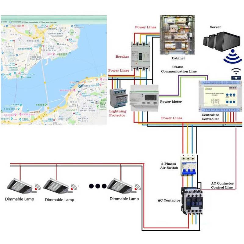
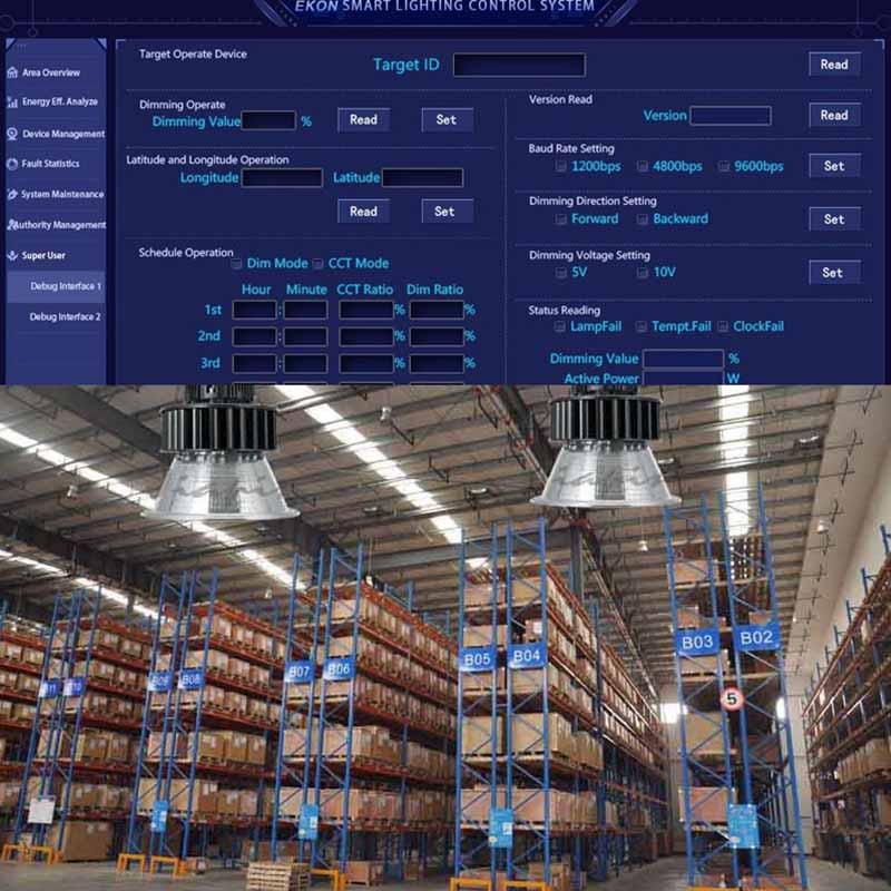
The system layer organizes terminal data into dashboards, alarms, reports, permissions, exports and maintenance records.
The owner-side center uses private server, wallboard or platform interface to review safety events, cost trends and service workflow.
Scope Definition
| Scope Item | Required Project Input | Why It Matters |
|---|---|---|
| Terminal selection | Pole type, current range, cabinet space, circuit count and load type. | Prevents treating the terminal as a generic consumer breaker. |
| Communication path | RS485, Modbus, gateway, local touchscreen, app, web dashboard, private server or customer platform. | Defines how field data moves into the system and operations-center layer. |
| Control authority | Who can switch, what can be switched, local override rule and returned-state requirement. | Keeps remote control traceable and suitable for facility management. |
| Report fields | Circuit name, load group, alarm type, energy period, cost logic and export format. | Turns measurements into owner-readable records and management decisions. |
Deployment Route
| Step | Engineering Action | Owner Record |
|---|---|---|
| 1 | Standardize site circuit names and load groups | Record the decision in the project handover file for interconnected energy management system. |
| 2 | Install terminal layer for key circuits in each branch | Record the decision in the project handover file for interconnected energy management system. |
| 3 | Create headquarters dashboard and monthly comparison reports | Record the decision in the project handover file for interconnected energy management system. |
| 4 | Use alarm records to drive maintenance action | Record the decision in the project handover file for interconnected energy management system. |
Owner Records
Panel, circuit name, load group, terminal model and current range should be kept as the basic asset record.
Alarm, switching command, returned state, abnormal value and service result should remain traceable after handover.
Report fields, user roles, cost assumptions and export templates should be clear to the owner.
Factory and site tests should confirm metering, protection behavior, communication, dashboard display and handover files.
Global Reference Logic
Global power-management platforms often frame the market around power monitoring, energy management, power quality, distribution visibility, asset status or enterprise software. STSYSTEMPLC does not need to copy that language mechanically. This page uses a clearer interconnected project-entry structure: terminal capability first, system workflow second and owner-side operations center third.
The content ties terminals to circuit identity, records, dashboards and owner workflow.
The page defines what is measured, controlled, recorded, integrated and accepted.
The language avoids unsupported superiority claims and focuses on deployable engineering boundaries.
Plain Engineering Answer
STSYSTEMPLC designs energy management as an interconnected terminal-to-headquarters workflow. Store-level terminals collect branch-circuit values and selected alarms. The system layer compares sites, load groups and reporting periods. The operations center gives owner headquarters a clearer view of energy cost, repeated electrical issues and maintenance priorities across many branches.
Technical Boundaries
| Boundary | Controlled Statement | Reason |
|---|---|---|
| Terminal rating | Selection must follow pole type, current range, load type and cabinet condition. | A project page should not imply universal terminal compatibility. |
| Remote control | Switching requires defined authority, local mode and returned-state records. | Facility control must be accountable. |
| Energy reports | Reports depend on circuit naming, baseline period and owner-selected cost logic. | Measured data needs context before it becomes a decision. |
| Integration | BMS, EMS, SCADA or private-server links require point lists and acceptance tests. | Integration is an engineering boundary, not a generic slogan. |
ENGINEERING MODEL
Identify the panels, circuits, loads, terminal locations, cabinet identifiers and operating areas included in the project owners, facilities, convenience sites and distributed facilities. Keep asset identity stable from survey through commissioning and handover.
Define the measurements, event states, timestamps, reporting periods, alarm priorities and historical retention required by the owner. Do not treat every available point as a required project point.
Separate monitoring from remote control. For any controllable load, define authorized users, local override, command expiry, returned-state confirmation, fail-safe behavior and the owner approval path.
The engineering objective is not simply to connect a smart terminal. It is to create an auditable path from field measurement to system interpretation and then to an owner decision. The selected architecture should remain understandable when a communication route is interrupted, a device is replaced, a configuration changes or responsibility moves from supplier to owner.
DATA AND EVENT FLOW
| Layer | Primary Responsibility | Acceptance Question |
|---|---|---|
| Field terminal | Measure the selected electrical values and report valid states with device identity and time context. | Can the owner verify the actual device, circuit and measurement boundary? |
| Communication | Move approved data and commands across the selected wired, gateway or network route. | What happens when the route is delayed, interrupted or resited? |
| System | Normalize points, create alarms, reports, permissions, trends and event histories. | Can the operator distinguish current state, stale state and confirmed returned state? |
| Operations center | Present owner-side decisions, exceptions, maintenance priorities and management records. | Can the owner export or retain the records needed for operation and audit? |
FAILURE AND RECOVERY
Disconnect a representative route and verify that stale data is distinguishable from a confirmed live state. Confirm the approved local behavior and recovery sequence.
Restart the relevant gateway or interface and confirm identity, time, configuration, point mapping and returned-state behavior after reconnection.
Replace a representative terminal and prove that the owner-approved configuration, asset identity and historical responsibility are resited correctly.
Test a central command against a local manual change and verify the authority, timestamp, expiry and reconciliation rule rather than assuming the last command won.
INTEGRATION AND HANDOVER
Provide device identity, circuit naming, point names, measurement units, alarm definitions, control permissions and the approved communication route for the delivered scope.
Preserve owner-approved settings, dashboard definitions, user roles, report logic, gateway configuration and the documented restoration procedure.
Retain factory checks, site commissioning records, abnormal-condition tests, exceptions, corrective actions and final sign-off authority.
Define who owns data, credentials, backups, software updates, replacement devices, integration changes and recovery decisions after handover.
OWNER / EPC / PROCUREMENT CHECK
Match the proposal to the selected panels, circuits, load types, current ranges and required measurement accuracy rather than using a generic device description.
Define owner, operator, integrator and supplier permissions and retain an auditable change history for every privileged action.
Choose cloud, private server, local server or owner platform according to project network policy, data-retention needs and integration responsibilities.
Agree in advance on the measurement points, alarm conditions, communication failures, recovery tests, reports and handover documents that constitute acceptance.
LONG-TERM OPERABILITY
Long-term operation depends on preserving the relationship between physical assets, electrical circuits, software points and owner decisions. A maintainable deployment keeps device identity, configuration backups, change history, alarm rules and recovery procedures accessible to the authorized owner. When a panel is modified, a terminal is replaced or a third-party platform changes, the project record should make the affected dependency visible instead of relying on supplier memory.
Record what changed, who approved it, when it was applied and how the resulting field state was verified.
Keep a tested owner-accessible configuration backup and a documented restoration route.
Handover should provide enough documentation and access for an authorized successor to operate and recover the system without hidden supplier dependencies.
FAILURE-MODE VERIFICATION
| Failure Event | Test Trigger & Method | Required Engineering Result |
|---|---|---|
| WAN / Cloud Interruption | Disconnect the approved upstream WAN or cellular communication route under the project test procedure. | Approved local control logic, configured schedules and selected protection behavior continue according to the defined project design without continuous upstream connectivity. |
| Gateway Reboot | Initiate a controlled restart or power cycle on the selected gateway or interface. | Field circuits retain the project-defined safe behavior; gateway reconnection, identity and point mapping are verified after restart. |
| Server Isolation | Isolate the central operations server from a representative branch network. | Project-defined essential local functions continue without continuous active server polling. |
| Communication Recovery | Re-establish network connectivity after a representative interruption. | Available buffered records are synchronized according to the configured data-retention and recovery design. |
| Power Restoration | Simulate cabinet power loss by power restoration where permitted by the approved test method. | Configured startup sequence, safe-state logic and returned-state behavior are verified after power restoration. |
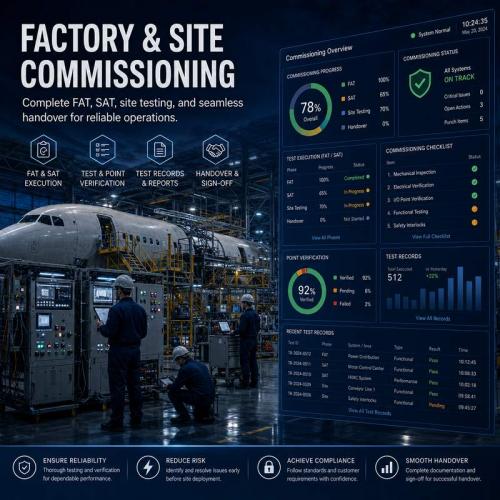
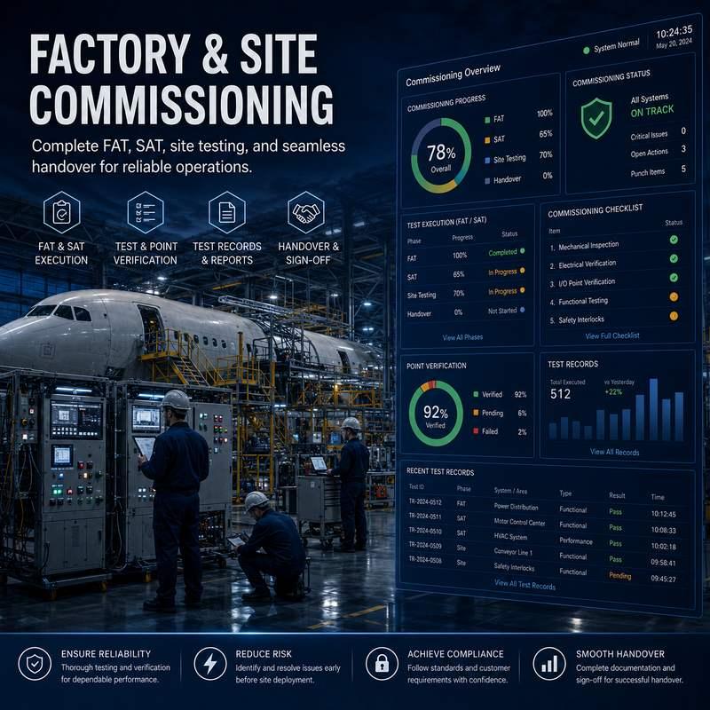
FACTORY TEST & SITE COMMISSIONING
| Test Item | Witness Method | Pass Condition | Owner Record |
|---|---|---|---|
| Asset identity | Match physical cabinet, circuit label and terminal identity. | Every selected point maps to the approved asset list. | Signed asset and point map. |
| Measurement validity | Compare representative live values against the approved test instrument or reference method. | Values are within the agreed project tolerance. | Commissioning measurement sheet. |
| Timestamp behavior | Observe a field event and compare field, gateway and system time. | Event ordering remains understandable and traceable. | Time synchronization record. |
| Alarm creation | Generate representative abnormal conditions. | Correct point, severity, time and acknowledgement state appear. | Alarm test record. |
| Command authorization | Attempt an approved and an unauthorized control action. | Only authorized actions are accepted and recorded. | Permission test record. |
| Returned state | Issue a representative command and inspect the physical or confirmed state. | System distinguishes command sent from state confirmed. | Returned-state evidence. |
| Communication interruption | Interrupt a representative communication route. | Stale data is identifiable and approved fallback behavior occurs. | Failure and recovery record. |
| Gateway restart | Restart the selected gateway or interface. | Configuration, identity, time and point mapping recover correctly. | Restart acceptance record. |
| Configuration backup | Export the owner-approved configuration. | Backup is readable and associated with the delivered revision. | Backup archive index. |
| Report generation | Generate representative daily, monthly and exception reports. | Report fields, units and period boundaries match the approved design. | Report samples. |
| Third-party interface | Exchange representative points with the approved BMS, EMS, SCADA or API route. | Point mapping, direction and exception behavior are confirmed. | Interface test sheet. |
| Handover | Review records with owner or authorized successor. | Documents, credentials, responsibilities and recovery route are acknowledged. | Signed handover package. |
IMPLEMENTATION PLAYBOOK
Walk the actual electrical environment. Record cabinet identifiers, feeder arrangement, circuit naming, load type, available space, existing meters, communication conditions and any local operating constraints. A good survey prevents the later system from becoming a collection of unverified points.
Create a stable naming convention for panels, circuits, devices, load groups and sites. For multi-location deployments, define the same business meaning for equivalent points before dashboards and reports are designed.
Select the terminal, gateway, communication and server route from the measured environment. Separate normal operation from fallback behavior and define where each failure domain begins and ends.
Build point lists, alarm rules, user permissions, report definitions, control limits and data-retention settings against the approved project matrix. Avoid changing production logic informally during commissioning.
Test normal values first, then alarms, controls, communication interruptions, gateway restarts, device replacement and recovery. Record actual observations rather than only checking whether a software screen changes.
Transfer the asset map, configuration backup, point list, user roles, acceptance evidence, exception list, maintenance instructions and lifecycle responsibilities to the authorized owner.
This workflow keeps the project understandable to the next engineer. It also reduces the risk that a dashboard looks complete while the underlying asset identity, communication route, control authority or recovery procedure remains undefined.
ENGINEERING DECISION BOUNDARIES
| Evaluation Dimension | Cloud-Dependent / Generic Platform | STSYSTEMPLC Owner-Controlled Architecture |
|---|---|---|
| Data Ownership | May depend on external cloud services, vendor licensing or vendor-defined telemetry routes. | On-premise server, private cloud or closed local network can be selected according to project-defined data ownership and retention requirements. |
| Edge Independence | Centralized architectures may depend heavily on continuous upstream connectivity for selected functions. | Field terminals and gateways can retain approved local schedules, interlocks and selected protection logic according to project configuration. |
| Multi-Site Scaling | Site-by-site configuration can create inconsistent naming and point-mapping practices if project standards are not defined. | Standardized naming templates and repeatable gateway mapping support scalable multi-site deployment. |
| System Integration | Integration routes may depend on platform interfaces, licensing scope and project-approved access methods. | Project-defined integration can use supported industrial protocols, APIs or data interfaces according to the selected system configuration. |
OPERATING SCENARIOS
The operator should be able to see current status, recent measurements and meaningful exceptions without interpreting raw protocol traffic. The screen should make site, panel, circuit and device identity obvious.
For sites with scheduled operating patterns, define the expected baseline and the escalation route for an unusual load. Avoid declaring an abnormal event from a single unexplained reading without context.
Where leakage, overload, abnormal current or voltage events are monitored, the system should identify the affected asset, time, severity and response responsibility and retain the event history.
When a technician changes a terminal, breaker, contactor, cabinet or communication device, the record should connect the physical intervention with the resulting software state.
After communication returns, the system should reconcile timestamps, stale data, current state and queued or expired commands according to the approved project rule.
Reports should distinguish measured energy, selected cost assumptions, comparison periods and exceptions. A report is a decision aid, not evidence of savings by itself.
RESPONSIBILITY BOUNDARY
| Role | Typical Responsibility | Must Be Explicit at Handover |
|---|---|---|
| Owner | Operating policy, data authority, acceptance and lifecycle decisions. | Authorized users, retention policy and final acceptance authority. |
| EPC / Integrator | Topology, installation, point mapping, interface configuration and commissioning. | As-built drawings, point list, test results and exception closure. |
| Electrical Contractor | Physical installation, wiring, labeling and safe field work. | As-installed condition and electrical test evidence. |
| Platform Team | Dashboard, reporting, user roles and approved integration behavior. | Configuration revision and restoration procedure. |
| STSYSTEMPLC / Supplier | Supplied equipment, documented technical support and agreed product-level obligations. | Product documentation, support boundary and agreed service route. |
SCALABILITY
Start with representative panels, circuits and one complete reporting workflow. Prove measurement, alarms, controls and handover before multiplying the topology.
Convert the accepted point map, naming convention, dashboard layout and test procedure into a repeatable project template.
Apply the approved template to additional sites while preserving site-specific exceptions and keeping each branch or facility independently identifiable.
Use the operations center to compare exceptions and maintenance workload while keeping each physical asset traceable to its local electrical environment.
BUYER EVIDENCE CHECKLIST
Ask for the proposed topology, terminal selection basis, point list, communication route, control boundary, server option and acceptance method.
Witness representative measurement, alarm, control, returned-state and communication behavior against the agreed test sheet.
Verify actual field wiring, asset identity, dashboard mapping, alarm response, failure recovery and owner-visible records.
Confirm configuration backup, documentation, credentials, responsibilities, exception closure and the practical recovery route.
TECHNICAL REVIEW QUESTIONS
Confirm whether the monitored or controlled circuit is single-phase, three-phase, multi-pole, upstream or downstream of another protective device, and whether the proposed measurement boundary matches the electrical drawing. The software point name should never hide an uncertain physical topology.
Confirm cabinet temperature, available installation space, wiring method, protection arrangement, service access and the expected maintenance environment. Product selection should follow the actual panel condition instead of assuming every cabinet is equivalent.
Define whether a displayed value represents instantaneous current, voltage, power, energy, a derived status or an event. Specify units, update behavior, quality flags and the period used for reports so operators do not confuse a live reading with a validated historical total.
For every important alarm, define trigger, persistence, severity, acknowledgement, escalation, clearance and historical retention. A notification without an operational response rule is not a complete alarm design.
For controllable equipment, document the exact physical action, expected feedback, local manual behavior and what happens if feedback is absent. A command record should not be presented as proof that a physical load changed.
When BMS, EMS, SCADA, Modbus, RS485 or an API is involved, define the source of truth, point direction, data type, scaling, polling or event behavior and fault handling. Interface labels alone are not an integration specification.
The strongest project documents make the boundary visible before installation. They state what the supplied equipment is responsible for, what the integrator must engineer, what the owner must approve and what the factory and site tests will actually prove.
MAINTENANCE AND SERVICE
| Maintenance Event | Required Record | Verification after Work |
|---|---|---|
| Terminal replacement | Old identity, new identity, reason, date and configuration revision. | Measurement, communication and dashboard mapping checked. |
| Panel modification | Updated circuit list and electrical drawing reference. | Point mapping and alarm logic reviewed. |
| Gateway change | Gateway identity, route, software/configuration revision and backup. | Representative points and recovery behavior tested. |
| Contactor replacement | Contactor identity, load boundary and switching responsibility. | Command and returned-state behavior witnessed. |
| Report logic change | Changed formula, period, cost assumption or report field. | Before/after sample report retained. |
| User-role change | Authorized user, privilege, approver and effective time. | Permission test and audit history checked. |
COMMERCIAL AND TECHNICAL BOUNDARY
Monitoring and reporting can reveal operating patterns and exceptions. Savings claims require an agreed baseline, measurement period, operating conditions and calculation method. The presence of a dashboard alone is not proof of savings.
Compatibility depends on actual electrical topology, device ratings, communication interfaces, protocol mapping and project configuration. A generic platform statement should not be interpreted as universal compatibility.
Owner-controlled, private-server or closed-network deployment can support project security requirements, but the final cybersecurity posture depends on network architecture, credentials, update policy, segmentation and owner controls.
System availability depends on the complete chain of field devices, communication, gateway, server, power and network infrastructure. Acceptance should therefore include representative failure and recovery tests.
FIELD ENGINEERING QUESTIONS
Confirm the physical cabinet, feeder, branch circuit and load description against the approved schedule. Record any field discrepancy before software point mapping is finalized.
Confirm the operating voltage, current range, load behavior, protective devices, wiring arrangement and installation constraints that affect the selected terminal or interface.
Confirm the actual cable route, gateway location, network policy, addressing method and expected failure domains. Do not infer communication quality from a drawing alone.
Confirm who watches alarms, who authorizes control, who receives reports, who performs maintenance and who closes exceptions after commissioning.
Confirm the person authorized to witness measurement, alarm, control, communication failure, recovery and final handover. The acceptance authority should be known before testing begins.
Confirm how new panels, circuits, sites, users and third-party interfaces will be added without losing asset identity or historical responsibility.
ENGINEERING REVIEW SUMMARY
A deployable power-management project has a defined electrical boundary, a measured data boundary, an explicit communication route, a controlled authority model and a witnessed acceptance method. STSYSTEMPLC uses the Interconnected Terminal → System → Operations Center structure so the field device is not presented as an isolated product. The final configuration remains project-specific and should be confirmed against drawings, selected equipment, configured limits, network policy and owner acceptance requirements.
Physical asset → point name → event → report → owner decision.
Failure → approved fallback → reconnection → confirmed resited state.
Supplier support → integrator responsibility → owner-controlled operation.
PROJECT DELIVERABLES
Show the terminal layer, communication route, system layer, operations-center boundary and relevant external interfaces.
List device identity, circuit identity, point name, unit, direction, alarm meaning and approved control authority.
Preserve the delivered configuration revision, user roles, report definitions, gateway settings and approved operating parameters.
Keep factory tests, site commissioning, abnormal-condition tests, exceptions, corrective actions and final owner sign-off together.
Document communication recovery, gateway replacement, terminal replacement, configuration restoration and owner escalation routes.
For BMS, EMS, SCADA or other platforms, retain point direction, data type, scaling, interface ownership and exception handling.
State who owns credentials, backups, updates, replacement devices, software dependencies and future expansion decisions.
Give the owner a simple index connecting drawings, device records, configuration, test sheets, reports and support documentation.
FIELD AND OPERATING EVIDENCE
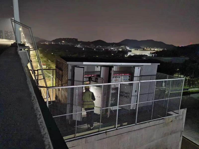
Review tunnel-scale operating context for field devices, cabinet coordination, controlled lighting behavior and owner-visible engineering records. Current-project topology, configured device limits, communication design and acceptance criteria remain project-specific.
STRATEGIC PARTNER-BRANDED TECHNOLOGY SUPPORT
STSYSTEMPLC supports qualified long-term strategic partners with partner-branded solution packaging, technical documentation, system integration support and owner-controlled deployment options for government, transportation, energy, industrial and security-sensitive infrastructure projects.
FAQ
No. The terminal is the field layer. The value comes from connecting terminal data with system dashboards, reports, permissions, records and an owner-side operations-center workflow.
Interconnected explains the project architecture more clearly than a generic smart-device label. It means terminal records, dashboard logic, alarms, reports and owner-side operations are designed as one deployable workflow.
Yes, project scope can include local touchscreen, app or web dashboard, private server, wallboard display or customer monitoring-center integration depending on the owner requirement.
Send branch count, typical panel layout, target load groups, reporting cycle, abnormal-consumption concern and headquarters dashboard requirement.
No. The deployment route can be selected according to project requirements and may include an owner-controlled local or private-server environment, an approved network service, or integration with an existing management platform.
A properly engineered control path should record the command source, timestamp, target, expiry or timeout behavior and the returned field state. A missing acknowledgement should not be treated as successful execution.
The project should define the approved local behavior, stale-data indication and recovery sequence for each controlled function. Acceptance should witness interruption and reconnection rather than relying only on normal-operation tests.
Provide the asset and point map, approved configuration, user permissions, backup and resite procedure, factory and site acceptance records, exceptions and corrective actions, and the documented lifecycle responsibility boundary.
RELATED SMART POWER MANAGEMENT ENGINEERING ROUTES
Send branch count, typical panel layout, target load groups, reporting cycle, abnormal-consumption concern and headquarters dashboard requirement.

Address : F4,Bldg A, Hanzhong Industrial Park, No.67, North of Xinsha Ave, Xin Tang, Zeng Cheng, Guang Zhou, China
Tel : +86 20 8278 0427
Email : info@stsystemplc.com
Email : morrison426@163.com