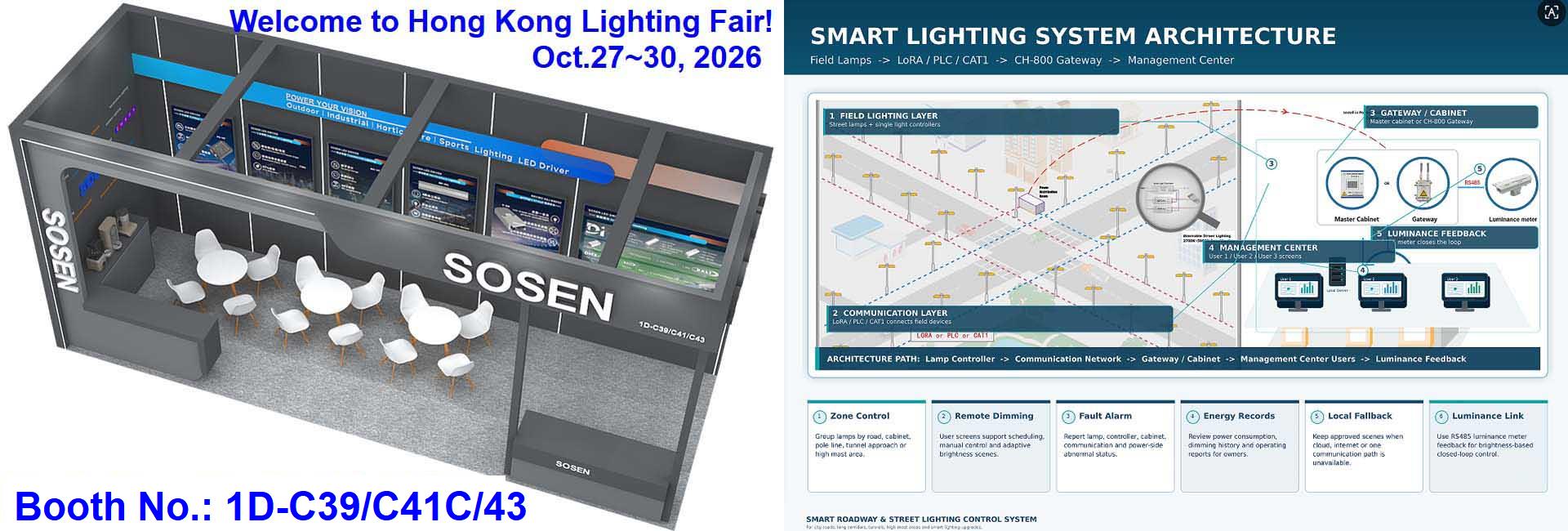
STSYSTEMPLC engineers an industrial-grade Interconnected Smart Street, Highway and Tunnel Lighting System for streets, highways, tunnels and long roadway corridors, connecting SLC810/SLC910 controllers, intelligent cabinets, CH-800 gateways, sensors, software and owner operations centers.
Hybrid OFDM PLC and LoRA communications, with project-selected NB-IoT, CAT-1, Ethernet or fiber routes, support monitoring, dimming, alarms, fault location and command feedback. City-scale and regional-corridor lighting networks can be organized by asset name, gateway zone, alarm priority, data owner and commissioning batch.
Schedules, sensing, tunnel policies and optional Adaptive CCT from 2700K to 6000K support controlled roadway operation. Local schedules and safe scenes can continue during communication interruption, while Factory Test & Site Commissioning protects handover.
For qualified strategic partners, STSYSTEMPLC can support Partner-Branded Solution Packaging and Owner-Controlled Deployment for Security-Sensitive Infrastructure Projects.
Engineer a large-scale roadway lighting network as one owner-controlled operating system—not as tens of thousands or hundreds of thousands of isolated luminaires. STSYSTEMPLC connects SLC810/SLC910 lamp-level controllers, interconnected intelligent lighting cabinets, CH-800 gateways, hybrid OFDM PLC and LoRA communications, selected cellular routes, centralized management software and an owner-side operations center within a controlled Terminal → System → Operations Center architecture.
EXECUTIVE SYSTEM OVERVIEW
A large-scale smart street lighting system should be evaluated as an interconnected field-to-operations architecture. The buyer should define luminaire quantity, road classes, pole and cabinet topology, control points, communication zones, server route, data ownership, offline behavior, third-party interfaces, failure recovery, factory testing, site commissioning and handover records before treating the proposal as technically complete.
FIELD AND OPERATING EVIDENCE
Review historical roadway-scale evidence for interconnected field devices, intelligent lighting cabinets, communication routes and owner-visible operating records. Current-project zoning, equipment limits, network design and acceptance criteria remain project-specific.
PROVEN AT LARGE INFRASTRUCTURE SCALE
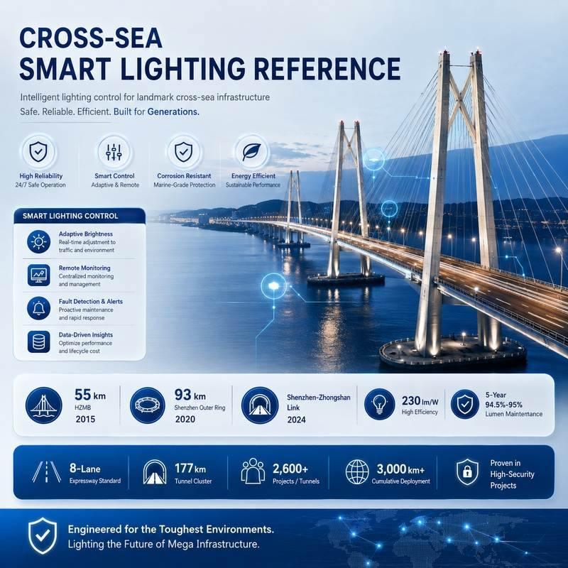
STSYSTEMPLC applies engineering practices developed through long-distance highway and tunnel deployments: stable asset identity, segmented communications, local operating logic, owner-visible records, abnormal-condition verification and controlled handover. Historical scale supports technical evaluation; every new tender still requires its own approved design and acceptance criteria.
SECURITY-SENSITIVE INFRASTRUCTURE READINESS
STSYSTEMPLC supports owner-controlled deployment for government, transportation, tunnel, municipal, energy and other security-sensitive infrastructure projects. On-premise servers, private-server deployment, local command-center operation, network segmentation, controlled remote access and closed-network environments can be engineered according to project requirements, integrator design and owner-side security policies.
Define cloud, private server, local server or owner platform before software and interface approval.
Separate monitoring, control, configuration, acknowledgement and administrative permissions.
Document zones, routes, firewalls, remote-support conditions and the source of truth for every external interface.
Handover credentials, backups, restoration procedures, update responsibility and auditable change records.
1K-100KPCS TENDER FRAMEWORK
A 1K-100Kpcs smart street, highway or tunnel lighting tender should be divided into traceable engineering zones rather than presented as one undifferentiated device count. The tender design should map every luminaire and controller to its pole, road section, cabinet, feeder, communication zone, gateway, server point, alarm rule, commissioning batch and owner record.
Municipal streets, highways, interchanges, bridges, tunnels, industrial roads and multi-zone public lighting networks.
Road authorities, municipalities, transport agencies, utilities, EPC contractors, system integrators and concession operators.
Luminaire schedule, road classes, poles, cabinets, feeders, communication constraints, server policy, interfaces and acceptance requirements.
Freeze one representative engineering template, verify it, then replicate it through controlled batches with site-specific exceptions.
The luminaire, pole, cabinet or feeder inventory is incomplete and no controlled survey or reconciliation process has been approved.
The proposal promises universal communication coverage, compatibility, energy savings or system capacity without project evidence and acceptance criteria.
Data ownership, remote-control authority, failure behavior, interface responsibility or final handover ownership remains undefined.
TENDER INPUT CONTROL
| Input Group | Required Information | Engineering Consequence |
|---|---|---|
| Road and lighting scope | Road type, road class, length, lanes, intersections, tunnels, bridges, pole quantity, mounting height, spacing, luminaire wattage and operating hours. | Defines lighting zones, asset count, scheduling boundaries and photometric review. |
| Electrical topology | Voltage, phase arrangement, cabinets, feeders, path circuits, protective devices, contactors, metering and grounding. | Defines cabinet equipment, control boundary, measurement meaning and safe field installation. |
| Control points | Lamp-level or circuit-level control, on/off, dimming, energy data, alarms, sensors, CCT functions and local override. | Defines controller type, point list, feedback requirements and acceptance tests. |
| Communications | PLC feeder routes, LoRA coverage, cellular availability, fiber/Ethernet backbone, frequencies, addressing and owner network policy. | Defines communication zones, gateways, failure domains and survey requirements. |
| Server and data | Cloud, private server, local center, retention period, operator count, audit requirements, reports and backup policy. | Defines platform architecture, storage, access, recovery and lifecycle responsibility. |
| Integration | Existing CMS, SCADA, traffic platform, API, point list, protocol, data direction, authentication and source of truth. | Defines interface scope, development responsibility and witnessed integration tests. |
| Acceptance | FAT, SAT, sample method, batch release, test instruments, witness authority, exceptions and handover deliverables. | Defines what constitutes a technically accepted system before commercial closure. |
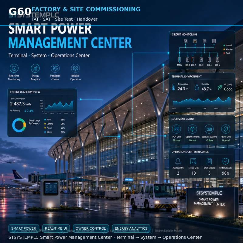
TERMINAL → SYSTEM → OPERATIONS CENTER
SLC810/SLC910 lamp-level controllers, cabinet-level controllers and project-selected sensors provide asset identity, approved control, measurement, status and event records at the physical roadway layer.
CH-800 gateways, intelligent lighting cabinets and selected OFDM PLC, LoRA, NB-IoT, CAT-1, Ethernet or fiber routes normalize field points into schedules, alarms, permissions, reports and maintenance workflow.
The owner-side center supervises zones, devices, exceptions, energy records, commands, users, interfaces and lifecycle actions through the approved cloud, private-server or local deployment route.
SCALABLE ENGINEERING MODEL
| Scale Object | Required Design Record | Acceptance Question |
|---|---|---|
| Luminaire and controller | Unique ID, pole ID, road section, wattage, interface, dimming range, firmware/configuration revision and commissioning status. | Can the operator trace a screen point to the correct physical pole and lamp? |
| Cabinet and feeder | Cabinet ID, feeder boundary, circuit list, protective arrangement, controller route and local operating logic. | Does every field point match the approved electrical drawing and installed circuit? |
| Communication zone | Selected medium, gateway, address plan, expected route, survey evidence, failure boundary and recovery rule. | Can a communication fault be isolated without losing asset identity or confusing stale data with live state? |
| Gateway | Gateway ID, connected zones, interface map, time source, configuration backup, local logic and restart procedure. | Does the gateway recover mapping, time and records after a witnessed restart? |
| Server and CMS | Hosting route, users, permissions, data retention, backup, reports, event volume and third-party interfaces. | Can the owner operate, audit, export and restore the delivered system? |
| Commissioning batch | Defined quantity, location, FAT release, SAT result, exceptions, corrective actions and sign-off authority. | Can each rollout batch be accepted or held without obscuring the status of the remaining project? |
ENGINEERING MODEL
Identify every road section, pole, luminaire, controller, cabinet, feeder, gateway, sensor and operations-center point included in the tender. Keep the same identity from survey and design through commissioning, maintenance and final handover.
Define required measurements, states, timestamps, quality flags, alarm priorities, reporting periods and historical retention. Do not convert every available controller value into a mandatory project point without an owner use case.
Separate monitoring from control. Define authorized users, target zones, local override, command expiry, returned-state confirmation, fail-safe behavior and the approval route for each controllable function.
The engineering objective is an auditable path from physical roadway asset to field signal, system interpretation, operator action and owner record. That path must remain understandable when a network route is interrupted, a device is replaced or responsibility moves from supplier to owner.
COMMUNICATION DECISION MATRIX
| Route | Typical Project Role | Engineering Verification |
|---|---|---|
| OFDM PLC | Uses the lighting power line for field communications where feeder topology and electrical conditions are suitable. | Verify feeder boundaries, phase arrangement, noise sources, cabinet coupling, path changes and representative end points. |
| LoRA | Supports project-selected wireless field links, supplemental coverage or sensor connectivity. | Verify permitted frequency, antenna position, obstructions, interference, link margin and representative route performance. |
| NB-IoT / CAT-1 | Supports selected independent cellular nodes or gateway backhaul where operator service is approved. | Verify carrier coverage, SIM ownership, tariff, lifecycle, signal at the installed location and behavior during service interruption. |
| Ethernet / Fiber | Supports cabinet, gateway, control-room or backbone connectivity within the approved owner network. | Verify addressing, switching, segmentation, redundancy, cybersecurity responsibility and physical route. |
| Hybrid architecture | Combines field and backbone routes for long corridors, mixed topology and phased migration. | Define the responsibility, priority, failure domain and recovery process for every route; hybrid must not mean undefined. |
LUMINAIRE AND CONTROLLER INTERFACE
Confirm supply, driver input, control method, auxiliary power, dimming behavior and returned-state capability for the selected luminaire.
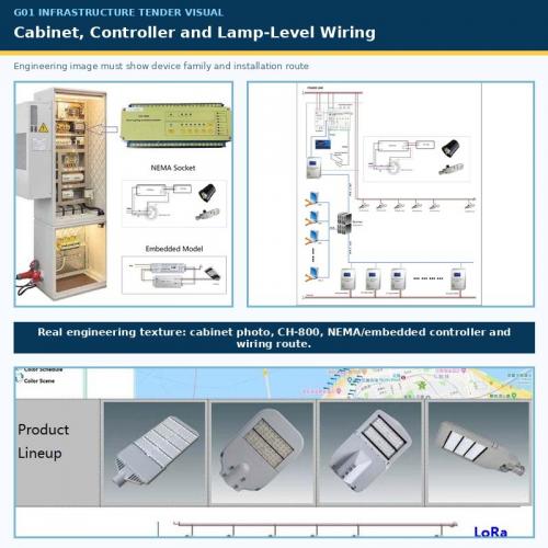
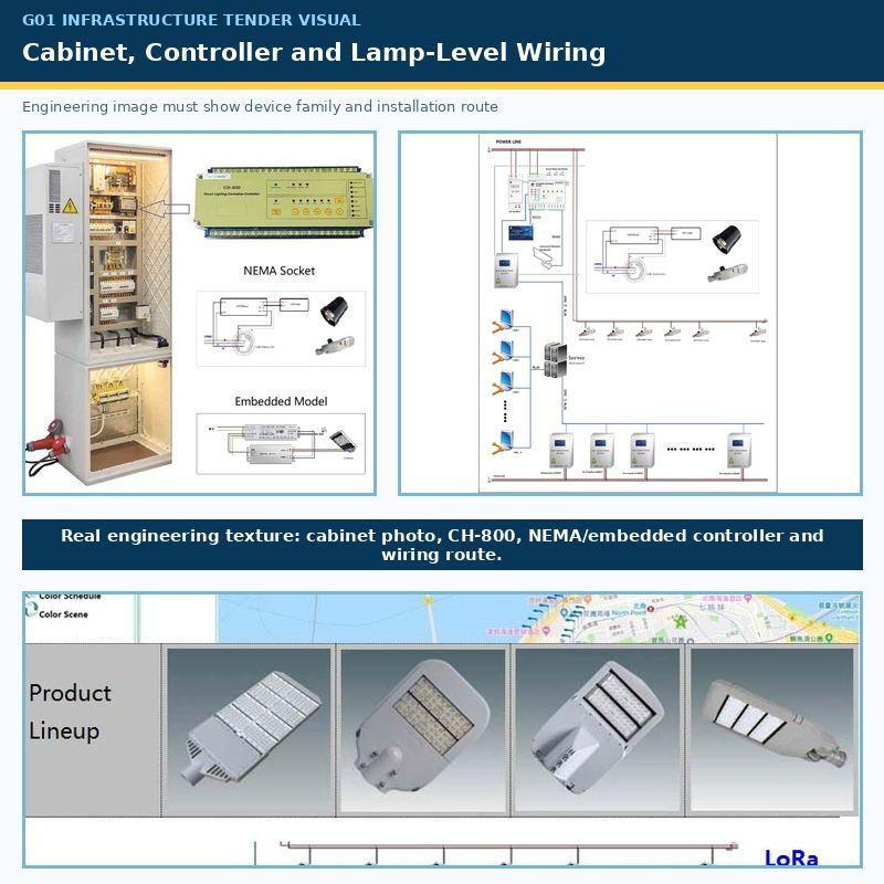
Confirm integrated controller, external enclosure, NEMA 5/7-pin or project-selected Zhaga interface against the submitted hardware.
Where DALI or D4i is specified, define supported functions, addressing, data access, commissioning and replacement behavior.
Keep the pole, luminaire, controller, configuration and historical record relationship visible when any component is replaced.
CONTROL AND OPERATING FUNCTIONS
Define sunset, sunrise, seasonal offsets, calendar exceptions and the local behavior used when upstream communications are unavailable.
Define zone, time, target level, transition, minimum safe level, override authority and the record that confirms execution.
Define sensor coverage, trigger zone, approved response logic, hold time, fallback and verification method before adaptive control is enabled.
Rain, fog, snow or low-visibility response must follow owner-approved inputs, priorities and lighting rules rather than an uncontrolled algorithm.
Where compatible luminaires are selected, project-defined CCT operation from 2700K to 6000K can support approved seasonal or weather scenes.
Define who may override schedules, the affected zone, expiry, confirmation, restoration and audit record for each action.
LIGHTING PERFORMANCE BOUNDARY
The control system must preserve the road authority's approved lighting classes and operating limits. Smart control does not replace photometric design. Road geometry, surface, traffic, conflict areas, luminance or illuminance, uniformity, glare, maintained performance and field measurement remain part of the lighting design and acceptance scope.
Identify motorized-traffic, conflict, pedestrian and special infrastructure zones under the applicable local or tender standard.
Associate each dimming scene with the approved maintained performance boundary, not only a percentage command.
Retain calculation files, luminaire data, design assumptions and project-defined field measurement records.
Define minimum levels, protected scenes, manual priority, sensor failure behavior and rollback conditions.
STANDARDS AND COMPLIANCE MAPPING
| Reference Area | Possible Tender Reference | Controlled Use in the Proposal |
|---|---|---|
| Road lighting performance | CIE 115, EN 13201 or the applicable national road-lighting standard. | Map the actual road classes, calculations, maintained values and field measurement method; do not claim one standard applies to every country. |
| Road and street luminaires | IEC 60598-2-3 and the applicable regional luminaire requirements. | Link every compliance statement to the selected luminaire model, certificate and submitted test evidence. |
| Digital lighting control | IEC 62386 / DALI-related requirements where specified. | State the exact supported control gear, control-device and data functions; avoid a generic DALI claim. |
| Outdoor controller interface | ANSI C136.41 / NEMA or Zhaga Book 18 where required. | Confirm the actual mechanical, electrical and communication interface of the submitted luminaire and controller. |
| CMS interoperability | TALQ Smart City Protocol or a project-defined API/point-list requirement. | Use certified or verified evidence where compliance is claimed; otherwise describe an integration route without implying certification. |
| Cybersecurity | Owner policy and applicable IEC 62443 principles or tender-specific controls. | Define zones, users, credentials, updates, audit, backup and lifecycle roles; do not imply certification without evidence. |
OWNER DATA AND INTEROPERABILITY
Pole, luminaire, controller, cabinet, feeder, gateway and CMS point identity should remain exportable and traceable.
Commands, returned states, alarms, acknowledgements, energy data and service actions should retain time and user context.
Owner-approved schedules, limits, roles, gateway mapping and platform settings should be backed up with revision identity.
Point direction, unit, scaling, authentication, exception handling and source of truth must be defined for external systems.
OPERATIONS-CENTER RECORDS
Distinguish confirmed live state, command sent, acknowledgement, stale data, local mode and unknown state.
Identify affected asset, trigger, severity, persistence, acknowledgement, escalation, clearance and assigned responsibility.
Define measurement boundary, period, units, missing-data treatment, comparison baseline and report assumptions.
Connect fault location, work order, technician action, replacement identity, retest and closure record.
Record user, target, time, reason, expiry, result and returned state for authorized remote actions.
Present zone status, exceptions, energy trends, response workflow and unresolved risks without hiding field uncertainty.
ENGINEERING DECISION BOUNDARIES
| Evaluation Dimension | Uncontrolled Project Risk | STSYSTEMPLC Project-Defined Architecture |
|---|---|---|
| Data ownership | Records may depend on external services, supplier-defined retention or inaccessible export formats. | Hosting, retention, export, backup and interface responsibilities are defined against owner requirements. |
| Edge independence | Selected functions may stop or become uncertain during WAN, cloud or server interruption. | Approved local schedules, essential logic, stale-state display and recovery behavior are assigned to defined field components. |
| System scale | Large device counts are imported without stable naming, zoning, batch release or exception control. | Asset templates, communication zones, point maps and commissioning batches preserve traceability through rollout. |
| Interoperability | Protocol names are listed without point direction, data meaning, authentication or acceptance tests. | Every required interface is tied to an approved point list, source of truth, responsibility and witnessed exception behavior. |
| Lifecycle control | Operation depends on supplier memory, hidden credentials or undocumented replacement procedures. | Owner handover includes configuration, credentials, backups, revisions, restoration procedures and lifecycle responsibilities. |
OWNER / EPC / PROCUREMENT CHECK
Separate luminaires, lamp controllers, cabinet equipment, CH-800 gateways, sensors, communications, platform software, server infrastructure, integration, commissioning and lifecycle support in the commercial and technical schedules.
Associate proposed quantities and zoning with the selected hardware and software revision, topology, data model, retention requirement and witnessed representative tests rather than a generic maximum-device statement.
Define owner, operator, EPC, integrator, network team and supplier permissions. Keep privileged changes, remote support and configuration revisions auditable.
Agree the asset map, normal functions, alarms, communication failures, recovery, reports, interfaces, batch release and handover documents before commercial commitment.
LONG-TERM OPERABILITY
Long-term operation depends on preserving the relationship between poles, luminaires, controllers, cabinets, gateways, software points and owner decisions. A maintainable deployment keeps configuration backups, change history, alarm rules, replacement procedures, credentials and recovery instructions accessible to the authorized owner instead of relying on supplier memory.
Record what changed, why it changed, who approved it, which assets were affected and how the resulting field state was verified.
Keep tested, revision-controlled backups for controllers, gateways and platform configuration with a documented restoration and verification route.
Provide enough access, documentation and training for an authorized successor to operate and recover the system without hidden supplier dependencies.
FAILURE AND RECOVERY OPERATIONS
Identify the affected asset, zone, communication route and time. Distinguish a failed lamp, controller, feeder, gateway, server route and missing data.
Apply the owner-approved local schedule, safe scene, manual boundary or maintenance process without extending an uncertain command into unaffected zones.
Restore the physical or communication path, confirm identity and time, reconcile current state with available buffered records and expire obsolete commands.
Record cause, affected assets, observations, corrective action, retest, remaining risk and the person authorized to close the event.
FAILURE-MODE VERIFICATION
| Failure Event | Witness Method | Required Engineering Result |
|---|---|---|
| WAN / cloud interruption | Disconnect the approved upstream route under the project test procedure. | Approved local schedules and selected essential logic continue; upstream data is shown as stale or unavailable rather than confirmed live. |
| Gateway restart | Initiate a controlled restart or power cycle of a representative CH-800 or selected interface. | Field zones retain the project-defined safe behavior; identity, time, point mapping and records recover correctly. |
| Server isolation | Isolate a representative field network from the central server. | Defined local functions continue without continuous server polling; the operations center identifies the affected boundary. |
| Field communication loss | Interrupt a representative PLC, LoRA, cellular or wired route. | The affected asset and zone are identifiable; commands, acknowledgements and stale states are not confused. |
| Communication recovery | Restore the route after a controlled interruption. | Current state is re-established and available buffered records synchronize according to the approved retention design. |
| Cabinet power restoration | Simulate approved power loss and restoration at a representative cabinet. | Startup sequence, local safe state, time, gateway mapping and returned-state behavior are verified. |
| Controller replacement | Replace a representative lamp or cabinet controller using the approved procedure. | Asset identity, configuration, communication, control and historical responsibility are resited without ambiguity. |
| Conflicting authority | Apply a central command while a representative local/manual condition is active. | Priority, authorization, expiry, feedback and reconciliation follow the approved control matrix. |
| Invalid or missing data | Introduce a representative unavailable, out-of-range or stale measurement. | The system displays quality and exception status without converting uncertain data into a confirmed operating fact. |
Factory Test & Site Commissioning
| Test Item | Witness Method | Pass Condition | Owner Record |
|---|---|---|---|
| Asset identity | Match pole, luminaire, controller, cabinet, feeder and gateway to the approved asset list. | Every selected point maps to the correct physical asset and drawing reference. | Signed asset and point map. |
| On/off control | Issue representative authorized commands across selected zones. | Target, authorization, execution and returned state are correctly recorded. | Control test sheet. |
| Dimming control | Apply approved dimming levels and transitions to representative luminaires. | Command, physical response and reported state match the approved tolerance and method. | Dimming acceptance record. |
| Schedule operation | Witness representative calendar, astronomical and exception events. | Correct zones execute the approved policy with traceable timestamps. | Schedule test record. |
| Measurement validity | Compare selected electrical values with the approved instrument or reference method. | Values meet the tender-defined measurement tolerance and boundary. | Commissioning measurement sheet. |
| Alarm creation | Generate representative lamp, cabinet, communication and electrical exceptions. | Correct asset, severity, time, status and acknowledgement workflow appear. | Alarm test record. |
| Command authorization | Attempt approved and unauthorized actions through representative user roles. | Only authorized actions are accepted; attempts and results remain auditable. | Permission test record. |
| Returned state | Issue representative commands and inspect the confirmed field state. | The system distinguishes command sent, acknowledged and physically confirmed state. | Returned-state evidence. |
| Offline local operation | Interrupt the approved upstream route while local schedules or essential logic are active. | Project-defined local operation continues and the operations center shows the correct data quality. | Offline-operation record. |
| Gateway restart | Restart a representative gateway. | Configuration, identity, time, mapping and available buffered records recover correctly. | Restart acceptance record. |
| Server and backup | Export the approved configuration and demonstrate the agreed restoration route. | Backup is readable, revision-controlled and associated with the delivered system. | Backup and restoration index. |
| Reports | Generate representative status, alarm, energy, maintenance and exception reports. | Fields, units, periods, missing-data treatment and assumptions match the approved design. | Accepted report samples. |
| Third-party interface | Exchange representative points and exceptions through the approved interface. | Direction, meaning, scaling, authentication and fault handling are confirmed. | Interface test sheet. |
| Batch release | Review completed tests and open exceptions for each deployment batch. | The batch is accepted, conditionally accepted or held under an explicit authority. | Batch release certificate. |
| Handover | Review documentation, credentials, training, backups, exceptions and responsibilities. | The owner or authorized successor can operate, audit and recover the delivered scope. | Signed handover package. |
PHASED DEPLOYMENT AND RELEASE
Create the compliance matrix, clarification register, responsibility boundary, tender topology and list of evidence required for every technical statement.
Select a zone that represents the actual luminaire, cabinet, feeder, communications, platform and interface conditions—not only the easiest installation.
Approve naming, asset templates, controller selection, gateway zoning, point lists, schedules, alarm rules, permissions and acceptance procedures.
Verify representative hardware, configuration, communications, controls, alarms, reports, failure behavior and documentation before shipment.
Install and accept controlled batches, preserve site exceptions and prevent unresolved problems from being multiplied across the rollout.
Transfer as-built records, configurations, credentials, backups, training, spare-parts route, open-item closure and support responsibilities.
IMPLEMENTATION PLAYBOOK
Compare tender schedules with actual roads, poles, luminaires, cabinets, feeders, network conditions and owner operating practices. Record discrepancies before final mapping.
Apply the approved naming, asset template, address plan, gateway zoning, point list and batch identity before devices enter the production system.
Load approved schedules, dimming rules, alarms, permissions, reports and interfaces under revision control. Avoid undocumented field changes during commissioning.
Verify physical identity first, then normal control, measurements, alarms, communications, failure behavior, recovery and owner-visible records.
Assign every failed or conditional item, record corrective action and retest the affected function before the batch is multiplied or released.
Issue the accepted asset map, configuration revision, test evidence, open-item status, backups and responsible signatories for each batch.
OWNER / EPC / INTEGRATOR RESPONSIBILITY
| Role | Typical Responsibility | Required Handover Evidence |
|---|---|---|
| Owner / road authority | Operating policy, road-lighting requirements, data authority, network policy, acceptance and lifecycle decisions. | Approved criteria, authorized users, retention policy, witness authority and final acceptance. |
| EPC / system integrator | System topology, interface coordination, field design, installation control, point mapping, commissioning and exception closure. | As-built drawings, asset list, point map, test results, deviations and closed exception register. |
| Electrical contractor | Cabinets, wiring, protection, labels, grounding, safe field work and installed electrical condition. | Electrical tests, installation records, circuit schedule and as-installed confirmation. |
| Network / platform team | Addressing, network access, hosting, security controls, users, integration, backup and recovery environment. | Network diagram, role matrix, interface record, backup and restoration procedure. |
| STSYSTEMPLC / supplier | Supplied equipment, product documentation, agreed configuration support, factory test support and defined technical service. | Product records, configuration package, agreed FAT evidence, manuals and support boundary. |
ENERGY, MAINTENANCE AND TCO
Record luminaire power, operating hours, zones, existing schedules, seasonal conditions and the agreed baseline period.
Associate each schedule or adaptive rule with approved lighting limits, expected hours and an auditable configuration revision.
Compare patrols, fault-location time, site visits, access equipment, replacement work, spare parts and closure records.
Include communications, hosting, SIM service, software support, backups, training, replacement devices and future integration.
MAINTENANCE AND SERVICE RECORDS
| Maintenance Event | Required Record | Verification after Work |
|---|---|---|
| Luminaire replacement | Old and new luminaire identity, driver/interface, reason, date and technician. | Electrical operation, dimming, controller link and CMS asset mapping checked. |
| Lamp-controller replacement | Old and new controller identity, configuration, firmware and pole relationship. | Communication, control, measurement, alarms and returned state witnessed. |
| Cabinet modification | Updated feeder, circuit, protection, controller and drawing reference. | Point mapping, schedules, alarms, local logic and recovery reviewed. |
| Gateway replacement | Gateway identity, connected zones, configuration revision, time source and backup. | Representative points, buffered records, restart and server communication verified. |
| Software/configuration change | Changed rule, approver, user, time, revision, reason and rollback route. | Before/after behavior and affected acceptance tests retained. |
| User-role change | User identity, privilege, approver, effective time and expiry where applicable. | Permission test and audit history checked. |
FIELD ENGINEERING QUESTIONS
Confirm pole number, location, luminaire model, driver, wattage, interface and controller identity against the approved schedule.
Confirm cabinet, phase, feeder, path circuit, contactor, protection, metering and grounding against the electrical drawings.
Confirm PLC electrical boundaries, wireless obstruction, antenna position, cellular signal, gateway location, backbone route and expected failure domains.
Confirm road class, pole geometry, sensitive locations, approved scenes, minimum safe levels and field-measurement requirements.
Confirm who watches alarms, authorizes control, performs maintenance, receives reports, approves changes and closes exceptions.
Confirm authorized witnesses, instruments, sample zones, test sequence, pass criteria and evidence format before site testing begins.
ENGINEERING DEPLOYMENT SUMMARY
A deployable roadway lighting project has a defined asset boundary, approved lighting boundary, explicit electrical and communication topology, controlled operating authority, owner-selected data architecture, verified failure behavior and witnessed FAT/SAT method. STSYSTEMPLC uses the Interconnected Terminal → System → Operations Center structure so every lamp controller, cabinet, gateway and software point remains part of one traceable owner workflow.
Road asset → field controller → communication zone → system point → operator action → owner record.
Failure → approved local behavior → controlled recovery → reconciled state → witnessed closure.
Supplier equipment → integrator delivery → authorized owner operation, data control and lifecycle decision.
PROJECT DELIVERABLES
Terminal, cabinet, gateway, communication, server, operations center and external interface boundaries.
Pole, luminaire, controller, cabinet, feeder, gateway, zone and commissioning identity.
Point name, unit, direction, source, quality, alarm meaning, severity and control authority.
Schedules, limits, users, reports, gateways, interfaces, revisions and approved backups.
Witnessed normal, abnormal, failure, recovery, interface and batch-release evidence.
Final drawings, installed identities, site changes, deviations and closed exception records.
Operator instructions, alarm workflow, backup, restoration, replacement and escalation procedures.
Credentials, training, spares, warranty route, software responsibility and future expansion boundary.
BUYER EVIDENCE CHECKLIST
Proposed topology, controller selection basis, capacity model, communication zoning, hosting route, interface scope, compliance matrix and acceptance method.
Representative identity, control, dimming, measurement, alarm, returned-state, offline, restart, interface and backup behavior.
Actual wiring, pole and cabinet identity, communication routes, CMS mapping, field response, failure recovery and operator records.
As-built package, configuration backup, credentials, training, exceptions, spares, recovery route and signed responsibility boundary.
STRATEGIC PARTNER-BRANDED TECHNOLOGY SUPPORT
STSYSTEMPLC supports qualified long-term strategic partners with partner-branded solution packaging, tender-oriented technical documentation, architecture and compliance support, system-integration coordination, factory test planning and owner-controlled deployment options for government, transportation, tunnel, energy and other security-sensitive infrastructure projects.
Partner-branded architecture, compliance matrix, technical schedules, clarification responses and controlled evidence packages.
Device selection, communications, interfaces, FAT/SAT planning, deployment batches and responsibility boundaries.
Private-server options, data ownership, documentation, configuration backup, handover and lifecycle support routes.
FAQ
Yes. The architecture is designed as a modular engineering framework for 1K-100Kpcs scale smart street, highway and tunnel lighting tenders. Final zoning, device selection, communications, hosting, interfaces and phased acceptance are defined from the actual tender schedule, drawings and project requirements.
No. The deployment can use an owner-controlled local or private-server environment, an approved cloud service or integration with an existing platform. Project-defined local schedules and essential behavior can remain at selected field components, subject to the approved configuration and acceptance tests.
Each controller should be associated with a stable pole, luminaire, road zone, cabinet, feeder, communication route, gateway and CMS point. Commissioning should use controlled batches with asset-map verification, normal-function tests, failure tests, exception closure and authorized release.
Migration can be evaluated after confirming luminaire drivers and interfaces, cabinet topology, protective devices, wiring, space, communication conditions and the required control and feedback points. Compatibility is an engineering result, not a universal claim.
The correct route depends on feeder topology, cabinet distribution, field survey, local frequency rules, cellular coverage, owner networks and failure requirements. OFDM PLC, LoRA, NB-IoT, CAT-1, Ethernet and fiber can be evaluated individually or as a controlled hybrid architecture.
Project-defined integration can be evaluated through supported protocols, APIs or data interfaces. The proposal should define the exact point list, direction, data meaning, authentication, source of truth, exception behavior, responsibilities and witnessed acceptance method.
The system should record the command source, user, timestamp, target, authorization, expiry, acknowledgement and returned field state. A command record alone should not be treated as proof that the physical luminaire changed state.
The approved design should define local schedules, essential operating behavior, stale-data indication, command handling, buffered records and the reconnection sequence for each failure domain. FAT/SAT should witness interruption and recovery rather than testing normal operation only.
Any savings estimate should identify the baseline, luminaire power, operating hours, dimming scenes, road-lighting limits, seasonal conditions, measurement boundary, calculation method and verification period. A dashboard or controller installation does not by itself prove a savings percentage.
The owner should receive the as-built architecture, asset and point map, approved configuration, user roles, credentials, backup and restoration procedure, FAT/SAT records, interface records, training, exception closure, spare-parts route and lifecycle responsibility matrix.
Send the tender requirements, country and applicable standards, luminaire schedule, road and pole data, cabinet and feeder drawings, communication constraints, server policy, interface list and required FAT/SAT records for an engineering review.

Address : F4,Bldg A, Hanzhong Industrial Park, No.67, North of Xinsha Ave, Xin Tang, Zeng Cheng, Guang Zhou, China
Tel : +86 20 8278 0427
Email : info@stsystemplc.com
Email : morrison426@163.com