Recommended direction: design the corridor as a sequence of engineering zones rather than one continuous communication bus or thousands of independent poles. Each zone should have a defined user profile, sensing method, forward-lighting behavior, power boundary, communication path, local fallback, weather policy, alarm scope and acceptance method.
For procurement, the important question is not whether a platform can display thousands of dots on a map. The important question is whether the owner can prove how the route behaves when a cyclist approaches a bend, when a group occupies several zones, when a communication path is interrupted, when the external network is unavailable, when weather conditions change, and when maintenance staff need to restore a replaced controller years after handover.
| Decision | Recommended Basis | Evidence Before Award | Acceptance Outcome |
|---|---|---|---|
| Control unit | Use a route zone, normally several coordinated poles, rather than one isolated luminaire. | Zone drawing, pole addresses, scene list, user classes and failure boundaries. | Correct neighboring poles respond together in both travel directions. |
| Detection | Match radar, motion or radar-video sensing to geometry, user mix and consequence of a missed event. | Coverage plot, target list, speed band, mounting geometry and nuisance-source review. | Required users are detected; missed and unwanted events are recorded. |
| Lighting response | Prepare a continuous visible route ahead with a controlled brightness transition. | Response-time budget, optics, dimming curve and maintained-light calculation. | Measured sensor-to-light response and route continuity meet the agreed values. |
| Communication | Choose PLC, LoRA or Hybrid PLC & LoRA by actual field condition. | Feeder topology, line-quality review, radio survey and interruption behavior. | Commands, alarms and fallback work under agreed injected failures. |
| Local autonomy | Separate essential field operation from continuous cloud dependency. | CH-800 rule list, stored schedules, data-retention boundary and restore method. | Approved local scenes continue during the defined upstream outage. |
| Lifecycle evidence | Treat records and backups as part of the delivered infrastructure. | FAT/SAT plan, alarm dictionary, asset export, configuration backup and handover index. | Owner can inspect, operate and restore the system after handover. |
A long corridor rarely has one physical condition from beginning to end. It may pass through straight low-use sections, blind bends, steep descents, event areas, urban interfaces, bridges, open terrain, maintenance gates and sections with different power or communication conditions. Copying one sensor range, one dimming level and one communication method across the entire route creates hidden risk.
Start with chainage, geometry, gradients, visibility constraints, pole positions, feeder boundaries, electrical quality, radio environment, user density, access points, weather exposure and maintenance responsibility. Then assign a zone type. The zone becomes the common reference for lighting calculations, sensor coverage, communication, alarms, asset records and FAT/SAT.
| Route Zone | Primary Risk | Control Direction | Lighting / Communication Response | Minimum Evidence |
|---|---|---|---|---|
| Straight low-use segment | Energy waste or late recognition of a lone slow user. | Bidirectional detection with conservative slow-user coverage. | Approved background scene; coordinated forward zone; PLC or LoRA selected by field condition. | Walk/ride tests, response timing, background level and communication record. |
| Blind bend or crest | User enters an unreadable section before the next pole responds. | Place detection upstream and overlap coverage around the visibility constraint. | Earlier activation; extended forward zone; stable communication across the bend. | Coverage plot, approach photographs, ride-through and measured scene response. |
| Steep descent | Higher approach speed reduces available response time. | Calculate upstream detection from approved speed and measured latency. | Longer look-ahead where required; avoid repeated drop-outs between zones. | Timed trials at the highest approved test speed. |
| Entrance / junction / crossing | Conflicting movements and side entry can bypass longitudinal sensing. | Use cross-path sensing or radar-video fusion where justified. | Priority or junction scene can override energy-saving scene under approved rules. | Multi-target test, event record, override and recovery. |
| Event / race section | Continuous riders can create scene oscillation or unnecessary switching. | Refresh occupancy while valid events continue; allow authorized event mode. | Stable event lighting for the approved period; controlled return to automatic operation. | Dense-group simulation, schedule test and restoration record. |
| Service / maintenance gate | Authorized vehicles and stationary work need different behavior. | Separate service policy from normal user policy. | Longer hold time, maintenance scene and operator authority. | Vehicle test, stationary-work scenario and timeout verification. |
| Weather-exposed section | Fog, snow, rain, dust or coastal mist changes visibility and sensing assumptions. | Use validated weather input and operator authority. | Evaluate normal 6000K and selected 2700K warm-light scenes with actual optics. | CCT, brightness, glare and transition records under representative conditions. |
The useful control unit is not the pole the user has already reached. It is the visible route ahead. When a valid target enters a sensing area, the current zone and selected neighboring zones should rise early enough to create a continuous corridor of light. Further detections renew occupancy; after the final valid event and hold period, the route returns gradually to the approved background scene.
This approach is especially important for bends, gradients and high-speed service access. A sensor can be technically “fast” while the overall system is still late if detection, communication, gateway processing, controller execution and luminaire rise time are not considered together.
| Operating Step | System Behavior | Design Question | Evidence to Review |
|---|---|---|---|
| Detect | Sensor identifies a valid event inside the configured field of view. | Which users, directions and speeds must be detected? | Coverage drawing, mounting height, target list and nuisance sources. |
| Validate | Local or gateway logic confirms the event against the approved operating rule. | Is the event sufficient to change the scene, or does it require persistence / fusion? | Rule table, event timestamp and configuration version. |
| Prepare ahead | CH-800 or local group logic raises the mapped forward zone. | How many poles or metres ahead are required for the approved speed and geometry? | Neighbor map, response budget and route calculation. |
| Maintain | Repeated valid events refresh occupancy and hold time. | Can groups travel through without premature dimming? | Dense-group test and event history. |
| Recover | The zone returns smoothly after the clear period. | What background level and transition rate preserve comfort and safety? | Scene file, dimming curve and site observation. |
| Record | Commands, events, alarms and energy data are retained according to scope. | Can the owner explain later why the route changed state? | Timestamped records and configuration baseline. |
Do not raise the lower speed threshold merely to suppress nuisance events. Pedestrians and slow cyclists on gradients must remain inside the approved detection envelope.
Continuous riders should refresh the occupied state. The route should not repeatedly fall to background between closely spaced users.
Forward zones must be mapped for both directions. A route that works only in one test direction is not accepted as a complete corridor design.
Detection distance should be calculated from the time available before the user reaches the section that must already be illuminated. Use the approved operating speed, route geometry, sensor coverage, measured system latency, dimming ramp and a documented safety allowance. Nominal sensor range should never be copied directly into a tender as an achieved safe look-ahead distance.
| Illustrative Speed | Equivalent Speed | 50 m Travel Time | 100 m Travel Time | Engineering Review |
|---|---|---|---|---|
| 10 km/h | 2.78 m/s | ≈ 18.0 s | ≈ 36.0 s | Slow-user detection and nuisance filtering become the main concern. |
| 20 km/h | 5.56 m/s | ≈ 9.0 s | ≈ 18.0 s | Typical cycling scenarios still require continuity across zone boundaries. |
| 30 km/h | 8.33 m/s | ≈ 6.0 s | ≈ 12.0 s | Verify sensor, communication, gateway, controller and luminaire response together. |
| 40 km/h | 11.11 m/s | ≈ 4.5 s | ≈ 9.0 s | Bends and descents require earlier detection and careful overlap. |
| 50 km/h | 13.89 m/s | ≈ 3.6 s | ≈ 7.2 s | Use only where the owner permits this service-vehicle test condition; measure the full response chain. |
Ultra-long corridor lighting becomes infrastructure when the complete chain is designed: sensing → field communication → gateway decision → lamp-level execution → alarm / energy / event record → maintenance action. If one link is undefined, the owner inherits a blind spot.
Radar, motion, radar-video, ambient-light and weather inputs provide project-defined events. The sensing scope should be limited to what is actually required and accepted.
CH-800 can organize route zones, schedules, scenes and local fallback so essential operation remains close to the field.
Single-lamp controllers apply switching or dimming commands and return status according to the selected interface and project architecture.
The IoT Lighting Platform provides map, asset, alarm, energy, schedule and maintenance views according to the contracted scope.
Route maps, logs, configuration versions, exports and acceptance files make operation reviewable after handover.
Operators retain manual priority for emergencies, maintenance, events and approved exceptional conditions.
Communication should follow the route, not a brand preference. New and electrically organized infrastructure can be favorable for PLC. Older areas may have decades of mixed wiring, multiple feeds, telecom cables and irregular power topology; LoRA can be practical there because it does not depend on the power conductor as the data path. An ultra-long corridor can contain both conditions.
| Engineering Item | PLC Only | LoRA Only | STSYSTEMPLC Hybrid PLC & LoRA |
|---|---|---|---|
| New organized infrastructure | Efficient where line topology and noise are controlled. | Can be deployed with radio planning. | PLC can be primary while LoRA provides an alternate path where the supplied architecture requires it. |
| Older / complex wiring | Performance depends on actual line quality, feeder boundaries and interference. | Often practical where rewiring is undesirable. | LoRA can take priority in difficult sections while PLC remains available in suitable zones. |
| Mixed long corridor | One communication family must fit every electrical section. | One wireless family must fit every radio environment. | Communication can be assigned zone by zone after electrical and radio review. |
| Field redundancy | Single field communication family. | Single field communication family. | Dual-channel designs can test PLC-to-LoRA or LoRA-to-PLC recovery under agreed conditions. |
| Local autonomy | Depends on controller architecture. | Depends on controller architecture. | CH-800 local rules separate essential field behavior from continuous upstream connectivity. |
| Acceptance | Measure line quality, command success and recovery. | Measure coverage, interference, command success and recovery. | Measure both supplied paths, transfer behavior, event records and restoration. |
Hybrid communication is not a claim that every packet travels simultaneously over two networks. The tender should state which channel is primary in each zone, what condition triggers alternate routing, how quickly the system identifies a failure, what continues locally, and what record the owner receives.
“Cloud connected” and “cloud dependent” are not the same architecture. A long public corridor should not require a remote server round trip for every basic lighting action. Where configured, CH-800 stores approved schedules and local rules so the field can continue essential operation during an external-network interruption.
| Failure Case | What Is Actually Lost | Required Local Behavior | Acceptance Test |
|---|---|---|---|
| Internet / WAN loss | Remote cloud communication. | Approved schedules and local scenes continue; records are retained according to scope. | Disconnect upstream link, observe field operation, restore and review retained records. |
| Cloud service unavailable | Central remote service. | Field rules continue inside the defined local boundary. | Simulate loss of remote service and verify operator / field behavior. |
| PLC path interrupted | One field communication route. | Affected zone follows the approved alternate or safe behavior; unaffected zones continue where topology allows. | Interrupt PLC on representative zone and record transfer / recovery. |
| LoRA path interrupted | One wireless field route. | Affected zone follows the approved alternate or safe behavior; unaffected zones continue where topology allows. | Interrupt LoRA on representative zone and record transfer / recovery. |
| Gateway fault | Local decision point is unavailable. | Affected boundary moves to the agreed safe state; fault is identified and configuration can be restored. | Controlled gateway failure and practical restore from owner-held backup. |
| Luminaire power loss | Field device cannot operate normally. | Communication redundancy cannot replace missing electrical power; alarm and power architecture determine recovery. | Power interruption test according to the project electrical design. |
Dedicated cabling over a long route can become a major civil and electrical cost. The corridor should compare grid, pure solar and Hybrid Solar-Grid together with distance, tariff, outage history, solar resource, battery autonomy, maintenance access and the operating scenes required at night.
| Power Model | Strength | Main Risk / Responsibility | Control Requirement | Procurement Question |
|---|---|---|---|---|
| Grid | Straightforward where stable power and practical feeder infrastructure already exist. | Long cable routes, outage exposure and energy cost. | Feeder / cabinet monitoring, schedules, dimming and outage alarms. | What is the lifecycle cost of extending and maintaining the electrical route? |
| Pure Solar | Can avoid grid extension in remote sections. | Seasonal solar resource, autonomy days, battery aging and panel condition. | Energy-aware scenes, battery protection and local autonomy. | What happens after several poor-generation days and how is battery health reviewed? |
| Hybrid Solar-Grid | Can combine solar generation, battery support and available grid power. | Priority logic, battery sizing, charging strategy and integration. | Local energy rules, outage scene, remote status and alarm records. | Can resilience be improved without oversizing the battery or relying on one energy source? |
For very long cable runs, voltage architecture and conductor sizing should be engineered separately. Where a project uses long-distance DC or AC distribution, the final choice must follow actual load, distance, voltage drop, protection, local electrical rules and maintainability.
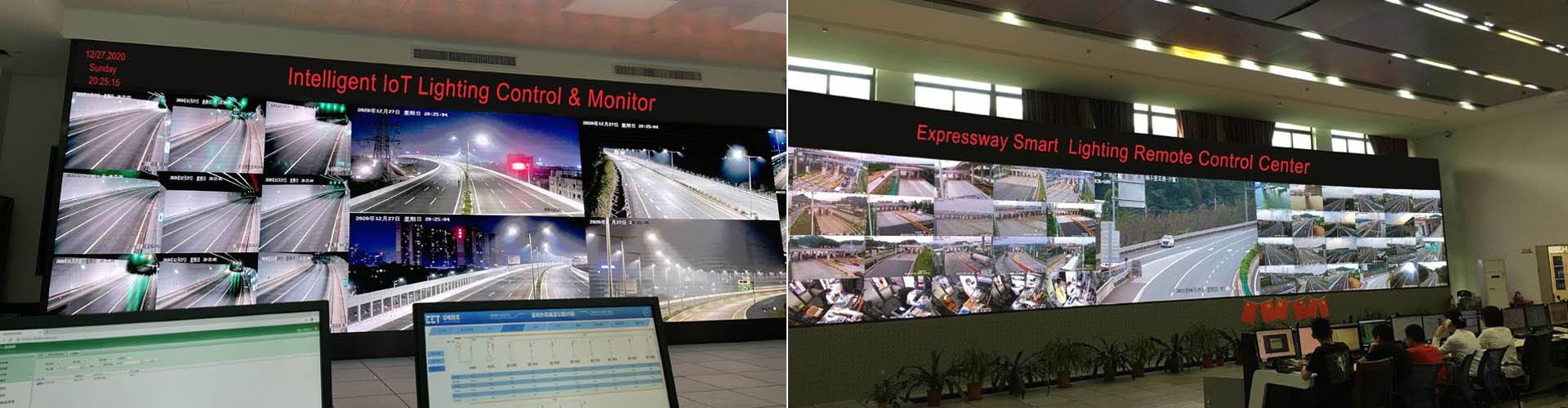
For an ultra-long corridor, scale evidence belongs near the center of the engineering argument. A long route magnifies every weakness in zoning, addressing, communication, commissioning, alarms and maintenance. The 93KM Shenzhen Outer Ring Expressway reference is therefore relevant as evidence of large distributed lighting infrastructure—not as a claim that a sports corridor should copy highway lighting levels.
93KM Shenzhen Outer Ring Expressway: full-width project evidence for long-corridor lighting control, Hybrid PLC + LoRA / sensor-networking experience and distributed field management. Transfer the architecture and operating discipline; verify sports-corridor optics, sensing and user behavior separately.
Adaptive corridor lighting is only credible when sensing is connected to a predictable field response. The BANYIN Freeway reference provides evidence of sensor-related coordinated lighting experience. For a sports corridor, the transferable method is the relationship between detection, zone logic, lighting response and field records.
BANYIN Freeway project reference: evidence of sensor-related coordinated field-lighting experience. Bicycle, pedestrian, motorcycle and authorized service-vehicle detection, route-specific scenes, nuisance behavior and response timing remain part of the new corridor FAT/SAT.
A reference video should never be stretched beyond what it demonstrates. It can support supplier capability and engineering method; it does not automatically prove every target type, every route geometry or every response time required by a new project.
Weather-responsive CCT should be governed like any other safety-related scene. The system can evaluate a normal white-light scene around 6000K and a warm-light scene around 2700K for selected fog, snow, rain or dust conditions where the optical design and field tests support that policy. CCT alone should not be presented as a universal visibility solution.
The complete chain should include weather input, CH-800 rule, brightness level, CCT scene, delay or hysteresis, manual override, sensor-fault fallback and event record. The owner should be able to see why the scene changed and restore the approved policy after maintenance.
Automatic Dual-CCT reference: 6000K normal scene ↔ 2700K selected adverse-weather scene. Verify the supplied luminaire hardware, weather-input method, brightness/CCT rule, transition behavior and measured photometric result for the actual corridor.
| Weather-Control Item | Design Requirement | Failure / Override Requirement | SAT Evidence |
|---|---|---|---|
| Weather input | Use the selected validated sensor or approved operator input. | Define behavior for invalid or missing input. | Trigger record and sensor-status check. |
| CCT scene | Define normal and adverse-weather target CCT by project policy. | Allow authorized manual override and safe fallback. | Measured CCT and scene transition. |
| Brightness | Coordinate dimming level with CCT rather than changing color alone. | Prevent an unsafe low-output weather scene. | Illuminance / luminance and uniformity record as applicable. |
| Delay / hysteresis | Avoid repeated switching around a threshold. | Define minimum hold and recovery behavior. | Threshold-crossing and recovery test. |
| Audit trail | Record scene change and source where contracted. | Retain enough information for operator review. | Timestamped event and configuration version. |
Infrastructure-grade content should separate demonstrated project facts from product capability, design proposals and assumptions that still require validation. This protects both the owner and the supplier from turning a reference project into an unsupported promise.
| Evidence Grade | Meaning | Acceptable Support | How It Should Be Written |
|---|---|---|---|
| A — Project verified | The stated function and scope are supported by identifiable project records. | Signed acceptance, approved drawing, test record, delivery list or owner-confirmed reference. | State the project and the specific verified scope; do not extend it to unrelated functions. |
| B — Product verified | A selected product capability is supported by current technical documentation or controlled test. | Datasheet, certificate, laboratory report, protocol document or witnessed FAT. | State model, configuration and limits; do not imply route performance without a site design. |
| C — Design proposal | A technically reasoned solution is proposed for this corridor but is not yet site accepted. | Calculation, coverage plot, control narrative, interface schedule and risk review. | Use proposed / designed to / subject to SAT and identify the open acceptance item. |
| D — Assumption / validation required | An input or outcome is uncertain and materially affects the design. | Assumption register with owner, due date and validation method. | Do not present it as achieved performance; show what changes if the assumption changes. |
Apply the same discipline to sensor speed bands, communication recovery, Dual-CCT, energy savings, solar autonomy and high-efficacy luminaires. A capability is not a project result until the relevant site conditions and acceptance evidence are available.
Global infrastructure buyers may evaluate Siemens, Cisco, Signify/Philips, Schréder, Schneider Electric, ABB, Telensa, Tvilight, Itron, Dimonoff and other established suppliers. These companies do not all compete from the same starting point: some are stronger in infrastructure automation or networking, others in professional lighting or connected-lighting management. A useful comparison therefore examines the exact offered corridor architecture rather than brand size.
| Supplier | Typical Infrastructure Position | What the Corridor Buyer Should Confirm | Acceptance / Lifecycle Focus |
|---|---|---|---|
| Siemens | Infrastructure automation and electrification. | Confirm the exact lighting-control package, field devices, communications and interfaces included in the offered project scope. | Review the offered FAT/SAT, data ownership, configuration responsibility and long-term support boundary. |
| Cisco | Networking and connected-infrastructure architecture. | Confirm how the network architecture integrates with lamp-level controllers, sensors, gateways and the lighting application layer. | Verify network availability, cybersecurity boundary, edge behavior and responsibilities during upstream-service loss. |
| Signify / Philips | Professional lighting and connected-lighting platforms. | Confirm the proposed luminaire, controller, sensor, communication and platform combination for the actual corridor. | Review scene control, device lifecycle, local fallback, platform records and project-specific FAT/SAT. |
| Schréder | Professional outdoor lighting and connected-lighting platforms. | Confirm the supplied field architecture, communications, sensing scope, interfaces and corridor-specific control logic. | Review commissioning, local operating behavior, asset records and handover responsibilities. |
| Schneider Electric | Energy management and infrastructure automation. | Confirm the exact boundary between electrical distribution, automation and lamp-level lighting control in the offered solution. | Verify power-system interfaces, controller autonomy, records and responsibility across the complete operating chain. |
| ABB | Electrification and automation. | Confirm the exact field-lighting devices, sensor integration, communication method and control scope proposed for the corridor. | Review interface ownership, commissioning tests, configuration control and lifecycle support. |
| Telensa | Connected street-lighting network and central management. | Confirm the project-specific field topology, route-zone behavior, sensing integration and recovery method. | Verify local operating boundary, communications recovery, data access and acceptance evidence. |
| Tvilight | Connected outdoor-lighting controls and smart-lighting management. | Confirm the proposed communication topology, sensor-to-light logic, local control and corridor integration. | Review response tests, failure behavior, configuration ownership and handover files. |
| Itron | Connected street-lighting and smart-city network management. | Confirm the supplied field-control scope, network architecture, interfaces and route-specific operating logic. | Verify network recovery, asset data, owner access, FAT/SAT and lifecycle responsibilities. |
| Dimonoff | Connected-lighting and smart-city control. | Confirm the supplied field devices, communications, sensing integration, local autonomy and application boundary. | Review alarm records, configuration, owner data, recovery tests and long-term support scope. |
| STSYSTEMPLC | Lighting-control-focused architecture: CH-800 gateway + lamp-level controllers + Hybrid PLC & LoRA + CAT-1/NB-IoT options + sensors + IoT Lighting Platform. | PLC, LoRA or Hybrid PLC & LoRA can be assigned by route condition. Motion, radar-video, ambient-light and weather inputs can map to route zones, light-ahead groups, local fallback and approved 6000K → 2700K scenes. | Route-zone tests, channel interruption, offline operation, sensor response, CCT scenes, alarms, asset exports, configuration backups and practical restore can be defined as FAT/SAT and handover items. |
Large infrastructure references are most useful when each one is tied to a specific procurement question. The owner should ask what the project demonstrates, what remains confidential or outside scope, and which new-corridor functions still require independent acceptance.
Long-distance smart road and tunnel lighting reference relevant to corridor-scale control, distributed field devices, communication topology and operating governance.
Large distributed deployment with approximately 28,000 terminals, relevant to gateway/node organization and field-device scale.
Cross-sea infrastructure reference where reliability, integration and lifecycle engineering are central project responsibilities.
Major bridge-tunnel infrastructure reference supporting review of complex transportation-lighting engineering capability.
Accumulated linear-infrastructure deployment experience relevant to zoning, communication, sensor integration and long-term maintenance thinking.
Sensor-related coordinated field-lighting reference relevant to adaptive-control method and sensor-to-scene engineering evidence.
Factory Acceptance Testing proves configuration and integration before delivery. Site Acceptance Testing proves the real corridor with its geometry, users, electrical supplies, communication conditions, nuisance sources and weather. Both stages should produce records that the owner can retain and use later.
| Acceptance Item | FAT Before Delivery | SAT on the Corridor | Owner-Held File |
|---|---|---|---|
| Asset identity | Map sensor, pole, controller, cabinet and gateway identifiers. | Check physical assets against route and platform records. | Asset list, route map and zone table. |
| User coverage | Define supported users, directions and sensing settings. | Test pedestrians, bicycles, motorcycles and authorized service vehicles where applicable. | Target-pass records and installed settings. |
| Bend / gradient | Prepare overlap and advance-lighting rules. | Traverse both directions at approved speeds and difficult approaches. | Route test, scene sequence and response timing. |
| Dense groups | Verify repeated-trigger and hold-timer logic. | Test sustained groups and simultaneous zone occupancy. | Detection history and no-premature-dimming result. |
| Radar-video linkage | Confirm event outputs, metadata interface and lighting-zone mapping. | Test entrance / junction activity, event alignment and lost-input fallback. | Integration scope, event/command log and recovery record. |
| Nuisance filtering | Prepare sensitivity, coverage and available filter settings. | Compare occupied and unoccupied periods with relevant nuisance sources. | Missed / unwanted trigger records and adjustments. |
| Photometric scenes | Validate luminaire configuration and scene limits. | Measure relevant light levels, uniformity and glare evaluation. | Photometric files and site measurement report. |
| PLC route | Verify line communication and command behavior. | Interrupt / degrade representative PLC path where testable. | Line-quality, command and recovery record. |
| LoRA route | Verify radio communication and command behavior. | Interrupt / degrade representative LoRA path where testable. | Coverage, command and recovery record. |
| Hybrid fallback | Verify both supplied paths and transfer logic. | Interrupt each supplied path on representative zones. | Transfer timing, event log and restoration record. |
| Outside-network loss | Load local schedules, scenes and fallback rules. | Disconnect external link and observe field operation. | Offline result, retained logs and restoration record. |
| Weather / Dual CCT | Check 6000K → 2700K rules and manual override. | Verify trigger, scene, recovery and measured output. | CCT scene file and weather-input test. |
| Power reserve | Agree backed-up scope and consumption assumptions. | Test selected outage and charging / reserve behavior. | Power test and reserve calculation. |
| Alarm closure | Prepare alarm dictionary and maintenance fields. | Simulate a fault through dispatch, repair and closure. | Alarm log and maintenance closure report. |
| Owner handover | Prepare accounts, exports, backups, interface notes and spare-parts plan. | Confirm owner access and practical restore demonstration. | Handover index, configuration backup and restoration result. |
The most expensive failure is not always a lamp fault. It can be the gradual loss of system knowledge: undocumented configuration changes, unknown controller identities, missing backups, unowned alarms and maintenance teams that no longer understand why a route behaves as it does.
Commissioning truth: route-zone map, asset baseline, scene logic, communication topology, FAT/SAT evidence and owner accounts are established.
Maintenance continuity: alarm history, replacement records, configuration backups, spare strategy and controlled changes protect operating knowledge.
Lifecycle resilience: exportable records, documented interfaces, staged upgrades and practical restoration reduce dependence on one engineer or one project phase.
| Lifecycle Risk | Weak Handover | Infrastructure-Grade Handover |
|---|---|---|
| Asset replacement | New controller is installed but not reconciled with route records. | Replacement identity, configuration and recommissioning result are recorded. |
| Staff change | Knowledge remains with the original commissioning engineer. | Owner retains route maps, configuration baseline, alarm dictionary and restore procedure. |
| Platform upgrade | Change is made without rollback evidence. | Version, backup, change scope and rollback path are controlled. |
| Communication change | Carrier / radio / feeder changes create unexplained blind zones. | Topology is updated and representative zones are re-accepted. |
| New event mode | Temporary race or event settings become permanent by accident. | Authorized scene has start/end authority and controlled restoration. |
| Audit / dispute | Feature claims cannot be traced to acceptance evidence. | Project claims link to FAT/SAT records, approved drawings or documented product capability. |
A corridor tender becomes stronger when the owner specifies operating outcomes rather than fashionable technology labels. Before award, the committee should be able to answer the questions below without relying on assumptions.
| Decision Gate | Question Before Award | Required Evidence |
|---|---|---|
| Project fit | Why does this corridor require adaptive / connected control rather than timer-only lighting? | Route use case, operating hours, safety needs, maintenance model and lifecycle objective. |
| Route zoning | How are bends, gradients, entrances, event areas and maintenance gates separated? | Zone drawing and control narrative. |
| User envelope | Which users and speeds are actually permitted and must be detected? | Approved target list and design-speed register. |
| Lighting continuity | How far ahead must the route be prepared and why? | Response budget, geometry and photometric calculation. |
| Communication | Which zones use PLC, LoRA, Hybrid or cellular connectivity and why? | Topology, surveys and interruption behavior. |
| Offline operation | What continues during each defined network failure? | Local-rule list and failure-mode test script. |
| Weather | When does 6000K → 2700K occur and who can override it? | Weather policy, sensor input, scene file and fallback. |
| Power | Which loads remain energized during an outage? | Power single-line, battery / hybrid strategy and reserve calculation. |
| Evidence | Which claims are project verified, product verified, proposed or assumed? | Evidence register with Grade A/B/C/D status. |
| Handover | What records and backups become owner assets? | Handover index, export sample and practical restore plan. |
For an engineering proposal, provide route geometry, bends and gradients, pole spacing, power availability, feeder boundaries, expected users, design speeds, event schedule, weather exposure, communication constraints and owner acceptance requirements. STSYSTEMPLC can map these inputs into route zones, communication architecture, adaptive scenes and a project-specific FAT/SAT plan.
Discuss the Corridor ProjectDownload Technical PDFs
Address : F4,Bldg A, Hanzhong Industrial Park, No.67, North of Xinsha Ave, Xin Tang, Zeng Cheng, Guang Zhou, China
Tel : +86 20 8278 0427
Email : info@stsystemplc.com
Email : morrison426@163.com