


Ground Swap Light Digital Industry Lighting System
Revolutionary Unmanned High Bay Light Installation, Removal & Digital Industry Lighting System
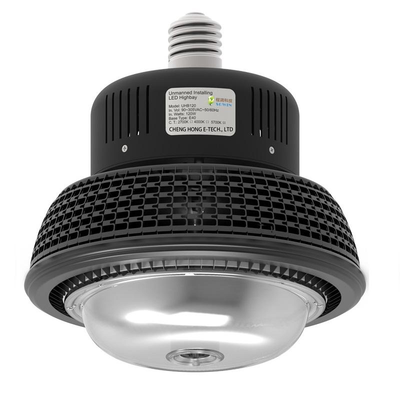
Ground Swap Light Digital Industry Lighting System is a ground-serviceable E39/E40 LED high bay system designed for facilities where routine lamp installation, removal and replacement should be evaluated from the ground-side maintenance layer. It combines a removable LED high bay terminal with a compatible telescopic handling tool, optional portable automatic lift, optional XYZ robot arm and an EKON digital lighting operations layer with floor-by-floor server visualization, independent luminaire IDs, weather-sensor inputs and motion-sensor dimming.
This is a project decision page for owners, contractors, engineers, distributors and OEM/ODM partners comparing light performance, service access, electrical safety, lifecycle cost and acceptance evidence before rollout.
Luminaire Terminal → Ground Service System → EKON Lighting Operations Center
Direct Answer for Google and Project Buyers
What Is a Ground Swap Light Digital Industry Lighting System Digital Industry Lighting System?
A Ground Swap Light Digital Industry Lighting System Digital Industry Lighting System is a ground-serviceable high bay lighting architecture in which a compatible E39/E40 LED high bay lamp can be engaged, removed, installed and re-seated from below by an approved service tool. Depending on ceiling height and site access, the service tool may be a telescopic handling pole, a portable automatic lift or an XYZ robot arm.
The system is intended to reduce the recurring access burden associated with selected high-ceiling lighting maintenance tasks. It does not eliminate electrical safety requirements, qualified-person boundaries or project commissioning. The verified result must include stable mechanical engagement, correct electrical contact, repeatable service cycles and owner-approved operating procedures.
Direct Answer Quick Check
Before using this solution in a quotation or project review, confirm these six engineering boundaries.
Facility FitWarehouses, factories, airport terminals, railway stations, logistics hubs and high-ceiling industrial buildings, ceiling height, fixture quantity, access restrictions and operating windows.
Lamp & SocketE39/E40 base, wattage, weight, thermal condition, electrical contact and existing fixture compatibility.
Service MethodApproved pole, automatic lift or XYZ robot route with obstruction, floor, safety-zone and operator checks.
EKON + SensorsServer floor map, independent lamp IDs, weather sensor, motion sensor, gateway route and returned-state visibility.
Reference LevelNuclear power station, large power plant, giant steel plant or other high-responsibility project experience when the buyer needs a top-tier digital industrial lighting review.
Acceptance RecordCycle test, Factory Test & Site Commissioning, training, spare-part list, server backup and owner handover file.
Controlled claim: “ground-serviceable” means the selected operating method is evaluated and accepted for the actual site. It does not mean every lamp, every socket or every building can be serviced from the ground without engineering review.
Owner-Side Business Problem
The Expensive Part of a High Bay Light May Be Access, Not the Lamp
High-Altitude Access Cost
A lamp replacement can require an aerial work platform, rental coordination, certified operator, route clearance, floor protection and a controlled work zone. For a small number of failed lamps, access cost may exceed the replacement lamp cost.
Production and Logistics Interruption
Racking, conveyors, forklifts, production equipment or public activities may need to be stopped or rerouted. The operational cost is therefore connected to timing, traffic and shutdown windows.
Safety and Responsibility Pressure
High-level maintenance creates responsibility for work-at-height planning, electrical isolation, access equipment, personnel qualifications and post-work inspection.
Scattered Failure Events
LED life does not mean all lamps fail at the same time. Scattered driver, socket or lamp failures can trigger repeated service visits across a large facility.
Future Spare-Part Uncertainty
The owner needs to know whether a replacement unit, compatible tool and service instruction will remain available after the initial installation.
No Acceptance Baseline
A demonstration may look successful, but without height, socket, torque, cycle and operator criteria, the project has no measurable definition of “serviceable.”
Infrastructure Proven
Evidence Must Progress from Concept to Owner Acceptance
| Evidence Level | What It Can Prove | Required Project Record | What It Cannot Replace |
|---|---|---|---|
| Operating concept | Shows that a lamp and service tool can engage, remove or install under a demonstrated condition. | Original video, product identity and stated demonstration condition. | Site-specific height, socket, access and safety approval. |
| Product engineering | Defines wattage, voltage, base, optics, thermal construction, weight, dimensions and control interface. | Controlled datasheet, drawing, bill-of-material boundary and quotation revision. | Repeatable operation at the buyer's facility. |
| Factory verification | Confirms representative mechanical service cycles and configured electrical performance before shipment. | Factory test checklist, sample identity, test result and exception log. | Actual site obstructions and operator workflow. |
| Site commissioning | Confirms the approved tool can reach, align, engage, remove and re-seat representative fixtures. | Commissioning checklist, fixture map, photo/video record and corrective actions. | Ongoing owner training and maintenance governance. |
| Owner acceptance | Confirms the final configuration, documentation, responsibility boundary and operating method are accepted. | Signed acceptance, training record, spare list, backup and handover package. | Future unauthorized changes or unverified substitute parts. |
Videos, patents and reference projects are supporting evidence. STSYSTEMPLC experience in nuclear power stations, large power plants and giant steel plants can support high-responsibility project review, but it does not replace approved topology or installation drawings, configured device limits, factory tests, site commissioning and signed owner acceptance.
Project Fit
Where Ground Swap Light Digital Industry Lighting System Creates Strongest Lifecycle Value
| Strong Fit | Conditional Fit | Not the First Choice |
|---|---|---|
|
Warehouses and logistics centers: high ceilings, clear vertical access and meaningful lift-related disruption. Factories and workshops: production equipment makes frequent elevated access difficult. Nuclear power stations, large power plants and giant steel plants: high-responsibility facilities need stricter lighting control, maintenance access, sensor logic, operating records and owner authority. Sports, exhibition and assembly halls: maintenance windows are limited and floor activities must be coordinated. Large multi-fixture facilities: repeated scattered failures create cumulative access cost. |
Aging E39/E40 sockets: inspect or replace before service approval. Strong vibration or dust: mechanical connection and ingress requirements need separate validation. Blocked vertical path: racking, cranes, ducts or machines may change the tool method. Wet or outdoor areas: the IP rating and socket enclosure must be confirmed for the environment. |
Projects that prohibit screw-base luminaires. Sites where every service event must use a certified aerial access method under local rules. Applications requiring sealed high-IP outdoor fixtures when only an IP20 reference product is offered. Ceiling geometry that prevents controlled tool alignment from below. |
Buyer Profile
Facility owners, warehouse operators, factory engineering teams, lighting contractors, MEP consultants, distributors, energy service companies and system integrators evaluating long-term maintenance architecture.
Trigger Event
New building design, high bay retrofit, repeated lift rental, difficult lamp replacement, a safety review, expansion to many fixtures or a requirement for lighting control and owner-side records.
System Architecture
Luminaire Terminal → Ground Service System → EKON Lighting Operations Center
1. Luminaire Terminal
Replaceable E39/E40 LED high bay, driver, heat sink, optical configuration, base interface and optional dimming/control interface.
Primary proof: electrical, photometric, thermal and mechanical compatibility.
2. Ground Service System
Telescopic tool, engagement head, portable automatic lift or XYZ robot method selected for height, access, alignment and service frequency.
Primary proof: repeatable engagement, removal, installation and re-seat confirmation.
3. Lighting Operations Center
EKON server software, optional weather sensors, motion sensors, PLC, LoRA, hybrid communications, scheduling, dimming, floor-by-floor visualization, fault visibility, energy data, independent luminaire IDs and owner-side interface.
Primary proof: mapped identities, returned state, role-based control, backup and records.
| Layer | Design Inputs | Outputs | Owner Decision |
|---|---|---|---|
| Luminaire terminal | Illuminance target, mounting height, voltage, CCT, CRI, beam, ambient temperature, socket and dimming. | Approved product schedule, light layout and configured model. | Does the lighting terminal meet both illumination and service-interface requirements? |
| Ground service system | Ceiling height, vertical path, floor condition, obstruction, lamp mass, tool reach and operator position. | Selected tool, operating procedure, training and service boundary. | Can the method be repeated safely and accurately under actual site conditions? |
| Operations center | Zones, schedules, sensors, communication path, user roles, reporting and integration boundary. | Control configuration, identity map, interface and owner backup. | Is digital control needed, and who owns configuration and ongoing support? |
Luminaire Terminal Engineering
The Replaceable Lamp Must Be Designed as a Serviceable Terminal
Base and Socket Interface
E39/E40 dimensions, thread condition, contact position, insertion depth, socket material, holding force and wear must be verified. Existing sockets should not be assumed acceptable based only on base name.
Mechanical Engagement
The service head must engage without damaging the heat sink, optical surface, driver enclosure or nearby structure. Engagement features need a repeatable orientation and release method.
Thermal Boundary
Rated life depends on ambient temperature, driver temperature, heat-sink airflow, operating hours and dimming profile. A life claim requires declared test conditions.
Optical Selection
Beam angle should follow mounting height, spacing, aisle geometry and illuminance calculation. A narrow beam can improve high-level delivery but increase uniformity risk.
Electrical Configuration
Input voltage, surge environment, power factor, harmonic limits, earthing, isolation and control interface must match local requirements and the actual circuit.
Replacement Consistency
Future spare lamps must preserve base interface, dimensions, center of gravity, tool engagement, optical distribution and electrical configuration.
Ground Service Method Selection
Choose the Tool by Verified Site Condition, Not Height Alone
| Service Method | Typical Project Condition | Engineering Checks | Acceptance Evidence |
|---|---|---|---|
| Telescopic handling pole | Lower-to-medium high ceilings, clear vertical approach, stable operator position and manageable lamp mass. | Reach, pole deflection, engagement visibility, alignment, torque control, tool head fit, operator posture and repeated cycles. | Representative-height test, cycle checklist, operator training and approved work instruction. |
| Portable automatic lift | Higher ceilings or conditions where a manual pole cannot provide stable alignment and controlled movement. | Floor flatness, transport route, deployed footprint, lift stability, rated height, emergency stop, alignment accuracy and storage. | Equipment inspection, height test, controlled service trial, safety boundary and maintenance schedule. |
| XYZ robot arm support | Advanced multi-fixture sites where repeatable mapped movements can justify engineering and commissioning cost. | Robot reach, fixture coordinates, collision zone, end-effector fit, torque, position tolerance, re-seat confirmation and recovery mode. | 1:1 fixture map, taught-position backup, exception test, returned-state proof and owner acceptance. |
| Conventional aerial platform | Exceptions, socket repair, electrical investigation or sites where ground-side service is not accepted. | Platform access, certified operator, floor loading, shutdown zone and local work-at-height rules. | Approved conventional maintenance method retained as a defined exception path. |
The 3–30 m statement is a project evaluation range covering different service equipment concepts. It must not be presented as one tool reaching every height or as automatic approval for every site.
Real Operating Evidence
Ground-Side High Bay Service Demonstration
The video shows the operating concept, engagement sequence and ground-side service intent.
Lighting and Electrical Design
Reference Product Data for Initial Engineering Discussion
| Item | Reference Source Value | Project Qualification |
|---|---|---|
| Product platform | Removable E39/E40 LED high bay light | Confirm socket, tool head and engagement compatibility by sample. |
| Power range | 50W–150W design options | Final selection follows illuminance calculation, spacing and thermal condition. |
| Example model | CHEHBU100W, 100W | Reference example only; production model and revision must appear in quotation. |
| Input | AC85–277V, 50/60Hz | Confirm project voltage, power quality, surge requirement and local compliance. |
| Luminous flux | Approximately 14,000 lm for the 100W reference | Use the controlled datasheet and test report for the quoted production version. |
| CRI | ≥80 reference | Higher CRI or application-specific color quality requires a separate configuration. |
| CCT | 3000K / 4500K / 6000K reference options | Do not combine fixed-CCT, selectable-CCT and 2700–6000K variable-CCT claims unless the exact version is confirmed. |
| Beam angle | 30° / 60° / 120° reference options | Select through mounting-height and uniformity simulation, not by preference alone. |
| Ingress protection | IP20 appears in the source example | Do not publish as a wet, washdown or harsh outdoor product unless a tested high-IP version is quoted. |
| Dimming | Dimmable configuration referenced | Confirm protocol, wiring, minimum level, driver compatibility and control topology. |
| Rated-life claim | Up to 100,000 hours appears in source material | Publish only with test method, ambient/thermal conditions, driver boundary and lumen-maintenance definition. |
| Warranty / construction | 5-year standard reference; aluminum body and black finish | Quote the final term, dimensions, mass, finish, exclusions and operating conditions. |
Lighting Operations Center
EKON Server, Weather Sensors, Motion Sensors and Digital Industry Lighting Layer
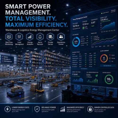
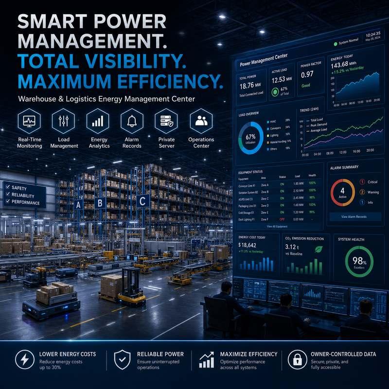
The digital layer can turn Ground Swap Light Digital Industry Lighting System from a maintenance solution into a digital industry lighting system. EKON server software can provide floor-by-floor visualization, independent luminaire IDs, weather-sensor inputs, motion-sensor dimming, schedules, alarms, energy records and returned-state visibility for owner-controlled operation.
Sensor and Local Control
Motion sensors, daylight inputs, process signals and weather-sensor logic can support 0–100% dimming when the driver and control design are compatible. The control sequence, priority rule and fail-safe state must be documented.
PLC Communication
Power-line communication may reduce additional signal wiring, but circuit topology, noise, phase conditions, coupling and device limits need project verification.
LoRA Communication
Wireless communication can support distributed points where radio coverage, interference, gateway placement, cybersecurity and local spectrum rules are accepted.
PLC + LoRA Hybrid
A hybrid approach can address different building zones. It requires a controlled topology and clear rules for which path owns command, state and recovery.
EKON Server and Floor Visualization
For multi-floor factories or buildings, the server can show each floor as an independent visual management interface. Every luminaire can carry its own ID, floor, zone, circuit, state, alarm and maintenance record.
Owner Interface and Digital Twin Map
Dashboards can provide floor maps, zones, schedules, alarms, energy information and returned states. Interface images are not proof until project identities, permissions, floor plans and field feedback are mapped.
Energy-Saving Boundary
A “70% saving” result can only be evaluated against a documented baseline including old load, occupancy, daylight, dimming schedule, operating hours and measurement period.
| Digital Acceptance Item | Required Proof | Owner-Held Output |
|---|---|---|
| 1:1 point identity | Each controlled fixture or zone maps to a physical location and configured device identity. | Point list, fixture/zone map and device schedule. |
| EKON floor visualization | Each building, floor, zone and luminaire ID is mapped to the server interface with visible status and approved naming. | Floor map, lamp-ID schedule, screenshots, backup file and owner access record. |
| Weather and motion sensors | Sensor input, dimming response, priority rule, manual override and fail-safe state are verified on site. | Sensor schedule, logic table, test screenshots and commissioning record. |
| Command and returned state | The interface distinguishes a command sent from the actual state returned by the field layer. | Commissioning screenshots and functional test record. |
| Role-based access | Administrator, operator, contractor and view-only permissions follow the owner's approved responsibility model. | User-role matrix and account handover record. |
| Configuration recovery | System configuration, device map and key parameters can be restored after approved failure scenarios. | Verified backup, restore method and revision record. |
Engineering Decision Boundaries
Compare the Maintenance Architecture Before Selecting the Lamp
| Architecture | Choose It When | Main Advantage | Decision Boundary |
|---|---|---|---|
| Conventional fixed high bay | Aerial access is already economical, failures are rare and operations can accept planned elevated work. | Simple familiar installation. | Does not reduce repeated access cost or work-at-height coordination. |
| Lowering winch system | Fixtures need to be mechanically lowered by cable to a service level. | Brings the whole fixture down. | Requires winch structure, cable routing, ceiling coordination and its own inspection regime. |
| Ground Swap Light Digital Industry Lighting System with pole | Compatible removable lamp and clear vertical access allow controlled engagement from below. | Low-complexity ground-side method. | Limited by reach, alignment, pole deflection, lamp mass, socket condition and operator workflow. |
| Ground Swap Light Digital Industry Lighting System with automatic lift | Greater height or alignment difficulty requires guided vertical motion. | Improved reach and movement stability. | Adds equipment transport, storage, inspection, footprint and operator requirements. |
| Ground Swap Light Digital Industry Lighting System with XYZ robot | High fixture count and repeated mapped service can justify automation engineering. | Repeatable position-based service potential. | Needs fixture mapping, collision control, recovery logic, tool calibration and site acceptance. |
| Fully integrated smart fixture | The project prioritizes networked control and is willing to replace the complete fixture during major service. | Purpose-built digital functions. | Smart control alone does not solve physical high-altitude replacement access. |
Failure-Mode Verification
Test What Happens When the Ideal Service Sequence Does Not Occur
| Failure Mode | Verification Question | Controlled Response | Acceptance Evidence |
|---|---|---|---|
| Worn or damaged socket | Can the socket maintain mechanical retention and electrical contact after representative cycles? | Inspect, measure and replace the socket; do not force lamp installation. | Socket inspection record and replacement rule. |
| Tool cannot align at actual height | Does deflection, visibility, angle or obstruction prevent full engagement? | Change tool method, operator position or use an approved exception access method. | Representative-height trial and approved method statement. |
| Under-seated lamp | Can poor seating be detected before normal operation? | Define visual, torque, electrical or returned-state confirmation appropriate to the design. | Re-seat check and post-installation functional test. |
| Over-torque or base damage | Does the service tool limit harmful torque? | Apply torque guidance, tool calibration or mechanical limiting features. | Tool check, sample-cycle record and damage inspection. |
| Lamp jams during removal | Is there a controlled stop and escalation path? | Stop operation; do not overload the pole, lift or robot. Move to approved manual/elevated inspection. | Exception procedure and responsibility assignment. |
| Obstacle enters service path | Can racks, forklifts, cranes, ducts or people create a collision risk? | Establish a controlled work zone and verify the vertical path before motion. | Access map and pre-service checklist. |
| Power remains energized | What isolation and verification are required before lamp service? | Follow owner and local electrical safety procedures; define qualified-person boundary. | Isolation procedure, authorization and training record. |
| Digital command without field response | Does the interface distinguish “command issued” from actual light state? | Use returned-state logic, alarm handling and local fallback. | Command/state test and exception log. |
| Communication or cloud loss | What lighting behavior remains available when the network path is unavailable? | Define local operation, safe default, buffered records and recovery procedure. | Offline test and recovery evidence. |
| Configuration loss | Can identities, zones, schedules and permissions be restored? | Restore from a verified owner-held backup under revision control. | Backup file, checksum/revision and restore test. |
Security-Sensitive Infrastructure Readiness
Keep Mechanical Service, EKON Server, Sensor Logic and Electrical Control Boundaries Explicit
Mechanical Boundary
Only approved lamp models, service heads, poles, lifts and robot end effectors should be used. Substitution requires compatibility review and recorded approval.
Electrical Boundary
Isolation, switching, socket repair, wiring changes and live-work restrictions remain subject to local rules and the owner's qualified-person policy.
Data and Control Boundary
When networked control is used, define EKON server ownership, floor visualization authority, luminaire ID records, user roles, remote access, password policy, firmware responsibility, log retention and system recovery.
The ground-service feature must not be interpreted as permission to bypass a facility's maintenance governance. A strong project separates what an operator may do, what qualified electrical personnel must do, what the integrator configures and what the owner accepts.
Factory Test & Site Commissioning
Scale Only After the Configured Product and Service Method Are Proven
| Stage | Minimum Test Scope | Go / No-Go Output |
|---|---|---|
| Engineering review | Site photos, ceiling height, fixture quantity, socket type, voltage, environment, obstructions, operating hours, access cost and local safety boundary. | Preliminary architecture, exceptions, required samples and test plan. |
| Configured sample | Quoted lamp model, base, dimensions, mass, optics, electrical input, dimming and engagement interface. | Approved or corrected sample specification. |
| Factory service-cycle test | Repeated engagement, removal, installation, seating, functional operation and inspection using the proposed service tool. | Cycle result, observed wear, limits and corrective action. |
| Pilot site test | Representative height, actual socket, vertical path, floor condition, operator workflow and normal/exception scenarios. | Pilot acceptance, modified method or project rejection. |
| Site commissioning | Fixture identity, electrical function, service method, digital control if used, failures, recovery, records and training. | Signed commissioning checklist and open-item register. |
| Owner handover | Approved configuration, spare lamp, tool, training, maintenance boundary, drawings, backups and acceptance evidence. | Owner-held handover package and responsibility transfer. |
Acceptance Rules
Define “Works” with Records the Owner Can Retain
| Acceptance Item | Pass Condition | Owner-Held Record |
|---|---|---|
| 1:1 fixture identity | Every approved position maps to fixture ID, model, wattage, base, height, zone and service method. | Fixture schedule and location map. |
| Configured product match | Installed units match the approved sample, quotation revision and controlled datasheet. | Product schedule, incoming inspection and serial/batch record. |
| Lighting result | Illuminance, uniformity, CCT, glare or other agreed criteria meet the approved project basis. | Lighting calculation and calibrated site measurement. |
| Ground service reach | The selected tool reaches and aligns at representative accepted positions without prohibited obstruction. | Height/access test checklist and video/photo record. |
| Removal and installation cycle | The lamp can be removed, inspected, reinstalled and functionally verified for the agreed number of demonstration cycles. | Cycle test sheet and exception notes. |
| Mechanical seating | The accepted method confirms adequate seating without visible damage or prohibited torque. | Inspection result and tool guidance. |
| Electrical safety boundary | Isolation, qualified-person tasks, operator permissions and prohibited work are documented. | Owner-approved method statement and training record. |
| Digital identity and roles | Where used, physical points map 1:1 to the interface and users have approved permissions. | Point list, role matrix and screenshots. |
| Returned-state proof | Commanded states can be distinguished from verified field states or clearly defined zone feedback. | Functional test and alarm/exception record. |
| Failure recovery | Selected socket, tool, communication and configuration failure scenarios have tested responses. | Failure test record and recovery procedure. |
| Configuration backup | Digital configuration, fixture map and robot positions, when applicable, are backed up and restore-verified. | Owner-held backup and revision register. |
| Handover completeness | Owner receives drawings, datasheets, spare list, operating instructions, acceptance and open-item status. | Signed handover index. |
Owner Records
The Deliverable Is a Maintainable System, Not Only Installed Hardware
Engineering Records
- Approved product datasheet and drawing
- Lighting calculation and fixture schedule
- Socket and service-tool compatibility record
- Electrical/control topology when applicable
- Configured limits and accepted exceptions
Test and Acceptance Records
- Factory test and sample identity
- Pilot and representative-height service test
- Site commissioning and corrective-action list
- Calibrated lighting measurements
- Signed owner acceptance
Operations Records
- Approved operating method
- Qualified-person and operator boundary
- Tool inspection and storage guidance
- Spare lamp and socket strategy
- Maintenance and exception workflow
Digital Records
- Point identity and zone map
- User-role matrix
- Configuration and robot-position backup
- Restore procedure and revision history
- Remote support and data ownership boundary
Responsibility Boundary
Who Must Confirm What Before Operation
| Party | Typical Responsibility | Not Automatically Assumed |
|---|---|---|
| Manufacturer / solution provider | Supply configured data, declared limits, service-equipment information, factory test scope and documentation. | Local electrical work, site access or operator qualification unless contractually assigned. |
| Distributor / integrator / contractor | Collect site inputs, coordinate samples, confirm installation, configure controls, execute tests and document exceptions within agreed scope. | Owner policy, building authority approval or hidden site conditions outside surveyed scope. |
| Electrical / lighting engineer | Review lighting result, electrical compatibility, circuit condition, socket selection, protection and local-code requirements. | Mechanical service acceptance without representative tool testing. |
| Facility owner / operator | Provide site information, access rules, qualified-person policy, operating constraints, acceptance criteria and ownership of handover records. | Unreviewed substitution, unauthorized operation or undocumented configuration changes. |
Controlled Claims
Publish What Can Be Verified and Qualify What Depends on the Project
| Avoid Unqualified Wording | Use This Controlled Wording | Evidence Needed |
|---|---|---|
| “Unmanned installing and disinstalling” | “Ground-serviceable installation and removal using a compatible approved service method.” | Configured product/tool test and site commissioning. |
| “No electrician required” | “May reduce dependence on aerial platforms for selected lamp service operations, subject to local electrical safety rules and qualified-person boundaries.” | Owner-approved procedure and local compliance review. |
| “Works from 3 to 30 meters” | “3–30 m project evaluation range across different service equipment options; final capability depends on height, access and verification.” | Tool limit, representative-height test and site record. |
| “Saves up to 70% energy” | “Energy savings depend on baseline load, occupancy, daylight, dimming strategy and operating hours.” | Baseline, measurement period and calculation method. |
| “100,000-hour life” | “Rated-life target subject to declared thermal, driver, operating and test conditions.” | Test method and production-version data. |
| “Suitable for all warehouses and factories” | “Designed for project evaluation in suitable high-ceiling facilities with compatible socket, access and environmental conditions.” | Project-fit review and approved exceptions. |
Strategic Partner-Branded Technology Support
OEM, ODM and Integrator Support for Local Project Delivery
STSYSTEMPLC can support qualified project partners with partner-branded solution packaging, configured product schedules, service-method explanations, technical drawings, lighting and control architecture, factory-test checklists, site-commissioning forms, RFQ inputs and owner-side handover records.
Commercial Positioning
Present Ground Swap Light Digital Industry Lighting System as a lifecycle maintenance system with a clear application boundary, rather than only a replaceable high bay lamp or an unsupported “no lift” promise.
Engineering Localization
Adapt voltage, wattage, optics, CCT, control, documentation, training and acceptance language to the target market and actual project configuration.
Partner branding does not change the evidence boundary. Product identity, configured limits, factory tests, site responsibilities and warranty terms should remain traceable in the project record.
FAQ
Common Questions About Ground Swap Light Digital Industry Lighting System
| Question | Answer |
|---|---|
| Is Ground Swap Light Digital Industry Lighting System a lamp or a complete system? | It is a system concept. The minimum configuration includes a compatible removable E39/E40 LED high bay lamp and an approved service method. Automatic lift, XYZ robot and digital lighting control are optional project layers. |
| Can the lamp really be changed from the ground? | It can be evaluated for ground-side installation and removal when the socket, lamp, service tool, height, alignment, vertical path and operator procedure are compatible and site-tested. |
| Does it eliminate aerial work platforms? | Not universally. It is intended to reduce lift dependency for selected routine lamp service operations. Socket repair, wiring work, obstruction, abnormal failure or local rules may still require approved elevated access. |
| Can it work at 30 meters? | Thirty meters belongs to the overall project evaluation range across different service equipment concepts. The approved capability depends on the selected pole, automatic lift or robot system and representative-height testing. |
| Can existing E39/E40 sockets be reused? | Possibly, but existing sockets must be inspected for dimensions, material, retention, contact condition, wear, temperature rating and service-cycle suitability. Replacement may be required. |
| What wattages are available? | The source material references 50W–150W options and a 100W example. Final wattage should follow lighting calculations, mounting height, thermal conditions and the quoted production model. |
| Can the system provide smart dimming? | Yes, suitable projects can evaluate sensor dimming, PLC, LoRA, PLC + LoRA hybrid communication and cloud-based operations. The communication topology and acceptance criteria must be project-specific. |
| What should be tested before a large order? | Approve the configured lamp and tool, run factory service cycles, conduct a representative-height pilot, verify normal and failure conditions, then complete site commissioning and owner handover. |
| What information is required for a quotation? | Provide ceiling height, fixture quantity, existing lamp and socket photos, voltage, environment, mounting geometry, obstruction, desired light level, control requirement, current maintenance method and preferred service equipment. |
RFQ and Pilot Evaluation
Send the Site Conditions Before Selecting the Service Method
Please provide ceiling height, fixture quantity, existing lamp and socket model, close-up socket photos, input voltage, operating hours, ambient condition, aisle/rack/equipment layout, clear vertical access, current lift or maintenance cost, required wattage/CCT/CRI/beam, dimming or control requirement, local safety restrictions and preferred pole, automatic lift or XYZ robot evaluation.
Recommended first step: select a representative pilot zone that includes the most difficult typical service condition. Define pass/fail criteria before the sample test.
SEO Publishing Fields
Short title:
Ground Swap Light Digital Industry Lighting System Digital Industry Lighting System
Expanded title:
Ground-Serviceable E39/E40 LED High Bay Maintenance and EKON Digital Operations System
Recommended URL:
/ground-swap-light-digital-industry-lighting-system.html
Page code: G65 · Mother page logic: Direct Answer → Infrastructure Proven → Project Fit → Architecture → Decision Boundaries → Failure Verification → Acceptance Rules → FAQ → RFQ.