other

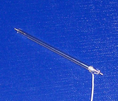
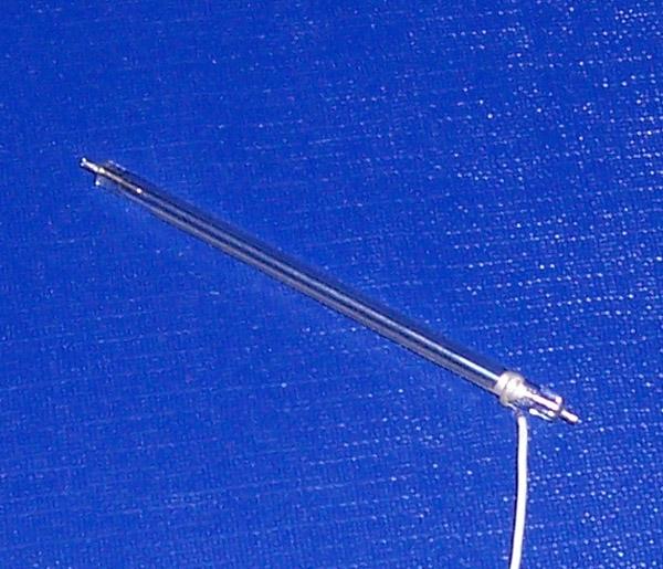
Analytical Instrument Xenon Flash Lamp

An Analytical Instrument Xenon Flash Lamp should be developed from the Instrument Requirement and Source-Module Architecture. The Spectral Region, Arc and Light-Center Position, Optical Coupling, Pulse Energy, Charging and Trigger Conditions, Repetition Rate, Acquisition Timing, Thermal Path, Mechanical Space, Insulation, Expected Life and Batch Control all affect the engineering route.

STSYSTEMPLC GXEC supports OEM Source Development, Controlled Alternatives, Legacy-Lamp Review, Identified Prototypes, Drawing Control, Lamp-Level Inspection and Long-Term Repeat Supply. The OEM remains responsible for complete Optical Design, Electronics, Calibration, Software, Safety, EMC and Regulatory Approval.

Engineering Entry Check
For an Engineering Review, send the following information:
Instrument: Function, Measurement Principle, Wavelength Region and Detector
Drawings & Optics: Source-Module Drawing, Optical Path, Light-Center Position and Available Space
Electrical & Timing: Capacitor, Charging Voltage, Trigger Method, Repetition Rate and Acquisition Window
Program & Supply: Environmental Conditions, Prototype Quantity, Annual Forecast and Required Documents
This page is for OEM analytical instruments designed around a pulsed xenon source. It does not claim a universal lamp, complete instrument accuracy or automatic compatibility with continuous xenon arc, deuterium, mercury or excimer-lamp systems.

Analytical Instrument Xenon Flash Lamp for OEM Source Module Development and Long-Term Supply

STSYSTEMPLC GXEC supports pulsed xenon flash lamp development for analytical-instrument manufacturers that need a new source, a controlled alternative to an existing lamp or a long-term spare-supply route. The page focuses on the lamp and its interface with the source module; it does not replace the OEM’s responsibility for complete optical design, electronics, calibration, software, safety and regulatory approval.

A practical development program starts with the instrument’s measurement objective. Required wavelength region, signal level, optical geometry, sample path, detector, acquisition timing, flash frequency, energy, warm-up behavior, battery or mains constraints, enclosure temperature and expected life determine the appropriate lamp route.

Compact and portable instruments may prioritize small source-module volume, low average power, short measurement time and repeatable light output. Benchtop or process instruments may prioritize wider spectral use, higher duty, serviceability, stable long-term supply and controlled batch characteristics.

Where a legacy lamp is involved, model, label, old-sample or source-module information from Heimann, EG&G, PerkinElmer or Excelitas-era supply contexts may help identify the historical route. These names describe supply history only and do not imply affiliation, original-part status or automatic compatibility.

For efficient engineering comparison: Prepare the optical, electrical, mechanical, timing, thermal, lifetime, prototype and supply requirements listed in the checklist and RFQ template below.

What Buyers Need to Know

An analytical instrument xenon flash lamp should be developed from the instrument requirement and source-module architecture. The key inputs are spectral region, arc position, optical coupling, pulse energy, charging and trigger conditions, repetition rate, acquisition timing, thermal path, mechanical space, insulation, expected life and batch control. Prototype testing must confirm the complete instrument signal, repeatability and operating cycle; lamp-level data alone cannot establish finished-instrument accuracy.

Engineering Reference Answer

An analytical instrument xenon flash lamp is a pulsed broadband source integrated into an instrument source module for absorbance, transmission, fluorescence, reflectance or other optical measurement. The lamp, drive circuit, optics, detector, acquisition sequence and software form one system, so lamp development must be tied to the intended instrument architecture.

The design inputs include spectral transmission, discharge geometry, arc and light-center position, pulse energy, trigger delay, repetition rate, envelope and lead geometry, holder interface, thermal path, insulation clearance, electromagnetic environment and the detector’s usable acquisition window. These variables affect signal, repeatability, life and manufacturability.

STSYSTEMPLC GXEC can support original-sample comparison, custom geometry discussion, identified prototypes, drawing control, lamp-level inspection and repeat-supply records. The OEM must validate optical performance, electrical safety, electromagnetic compatibility, calibration, software behavior, environmental operation and any regulatory requirements in the finished instrument.

Key Engineering Targets for OEM Source Development

Engineering Target What to Define Why It Matters
Spectral and signal requirement Required wavelength region, detector sensitivity, sample path and target signal window. Defines useful output rather than relying on total visible brightness.
Arc and optical geometry Arc length, light-center tolerance, orientation, lens, filter, fiber, slit, reflector and holder interface. Controls coupling efficiency and repeatability between instruments.
Discharge and timing Capacitor, charging voltage, stored energy, trigger method, delay, repetition rate and acquisition window. Determines pulse behavior, signal timing, stress and life.
Mechanical and thermal integration Envelope, leads, connector, clearance, mounting, enclosure, airflow and operating temperature. Prevents fit, insulation, heat and service problems.
Life and duty cycle Flashes per measurement, daily use, peak periods, expected flash count and allowable output change. Connects prototype performance with realistic service life.
Production and change control Approved sample, drawing, critical characteristics, incoming checks, batch identity and change notification. Protects the OEM from uncontrolled variation after qualification.

OEM Integration and Responsibility Boundary

Item STSYSTEMPLC GXEC Scope OEM or Instrument-System Scope
Xenon flash lamp Lamp-level geometry, discharge characteristics, sample development, inspection and repeat-supply records. Complete source-module electronics, optical architecture and finished-instrument acceptance.
Drive interface Discussion of capacitor, charging voltage, trigger method, repetition rate and lamp operating window. Circuit design, protection, EMC, creepage, clearance, firmware and safety approval.
Optical interface Arc position, spectral region, lamp orientation and coupling requirements provided by the OEM. Lens, filter, slit, fiber, detector, sample path, calibration model and algorithm.
Production route Approved sample identity, drawing control, lamp inspection, batch traceability and change notification. Finished-device quality system, regulatory files, field service and product liability.

Decision Risk: A Bench Flash Is Not an OEM Qualification

A lamp that ignites on a development bench has completed only the first step.
Changes in arc position, spectral transmission, pulse timing, thermal behavior, lead geometry or batch characteristics can alter the instrument signal, detector window, life, EMC behavior or assembly process even when the lamp appears similar.
The controlled route is to define the source-module interface, qualify identified prototypes through the full measurement and environmental cycle, then preserve the approved characteristics for repeat production.

20-Year Xenon Engineering Verdict
Why Pulsed Xenon Remains a Reference Source Architecture in Compatible Analytical Instruments
In an analytical instrument designed around pulsed broadband xenon, a short high-intensity discharge can support absorbance, transmission, fluorescence, reflectance or multi-band measurement through the instrument’s optics, detector and timed acquisition sequence. This architecture remains appropriate when the source module and measurement method were designed around that pulse behavior.
Decision boundary: LED sources can be highly effective in instruments designed around selected wavelengths, but they are not automatically drop-in replacements for a pulsed xenon architecture. The correct decision depends on the instrument design and verified system-level results.

Xenon vs LED — Analytical Instrument Source Engineering Parameters

Parameter Pulsed Xenon Flash Lamp LED / LED Array
Source behavior Broadband capacitor-discharge pulse in compatible analytical-instrument designs. Selected wavelength or multi-LED output controlled by the LED and driver architecture.
Spectral route Useful output is selected by envelope transmission, filters, optics, wavelength-selection components and detector response. Output depends on emitter wavelength, binning, temperature, optical mixing and driver control.
Timing Trigger delay, pulse shape and acquisition window must match the measurement sequence. Driver timing, rise/fall behavior and thermal regulation must match the measurement sequence.
Integration boundary Main risks include arc position, pulse energy, trigger coupling, envelope transmission, insulation and duty mismatch. Main risks include wavelength coverage, driver redesign, optical mixing, thermal margin and recalibration.
Approval rule Use the source architecture specified by the instrument unless a complete optical, electrical, software and calibration redesign is validated. The same approval rule applies.

1,100-Hour Endurance Proof — Engineering Boundary
Lamp-Level Endurance Evidence Must Not Be Misread as Finished-Instrument Approval
Validation Path Engineering Meaning
Strict endurance program A lamp-level endurance program exceeding 1,100 hours under defined operating conditions, focused on ignition stability and controlled aging behavior.
Risk-control matching Geometry, trigger route, pulse energy, repetition rate, temperature and endurance level are reviewed to reduce hidden misfire, blackening and early-life failure risk.
Scaling path Engineering samples, source-module verification, pilot quantity, repeat-supply checks and field feedback expose failure modes before regular production.
Evidence boundary: The result from more than 1,100 hours of testing does not by itself prove finished-instrument accuracy, calibration compliance, EMC, safety, regulatory approval, universal service life or compatibility with every analytical instrument. The OEM must complete its own qualification program.

Qualification and Validation Route

Stage What Should Be Confirmed Useful Records
1. Instrument requirement Measurement function, wavelength region, signal window, detector, optical path, source-module volume, power and life target. Requirement sheet, block diagram, mechanical drawing, optical layout and use profile.
2. Lamp and drive definition Envelope, arc position, leads, holder, stored energy, charging, trigger, repetition rate, timing and thermal route. Lamp drawing, circuit conditions, waveform, tolerance list and sample identity.
3. Prototype integration Mechanical assembly, insulation, optical alignment, startup, signal, timing, temperature and serviceability. Build photographs, integration notes, waveform and initial measurement data.
4. Instrument qualification Repeatability, spectral or reference checks, environmental operation, duty cycle, life trend and relevant safety or EMC tests. Qualification plan, test data, calibration record, environmental and compliance reports.
5. Production release and supply Approved sample, drawing, critical characteristics, incoming checks, batch traceability, change notification and annual forecast. Retained sample, signed drawing, inspection criteria, batch record and field feedback.
Responsibility boundary: STSYSTEMPLC GXEC supports lamp-level design input, sample development, inspection and repeat-supply control. Complete source-module design, finished-instrument performance, safety, EMC, calibration, software and regulatory approval remain with the OEM.

Failure Symptoms, Possible Causes and Verification

Observed Issue Possible Causes Verification Route
Prototype signal is lower than expected Spectral mismatch, arc position, optical coupling, pulse energy, detector timing, filter loss, sample path or detector sensitivity. Measure the relevant spectral or detector signal, inspect alignment, compare timing and evaluate the complete optical path.
Instrument-to-instrument variation Light-center tolerance, holder stack-up, optics, circuit variation, detector variation or software normalization. Use a controlled lamp sample, mechanical gauge, optical alignment check, waveform comparison and system-level correlation.
Intermittent ignition or timing error Trigger coupling, charging recovery, wiring, insulation, firmware sequence, temperature or component tolerance. Capture trigger and discharge timing, check hot and cold starts, inspect wiring and compare repeated operating cycles.
Life is shorter than expected Excess energy, flash rate, thermal stress, unsuitable duty cycle, electrode loading or acceptance threshold. Review stored energy, repetition profile, enclosure temperature, waveform, flash count and signal trend.
Production batches behave differently Uncontrolled material, geometry or process changes, or incomplete incoming correlation. Use approved samples, critical-characteristic limits, batch identity, incoming checks and change notification.
Important: A symptom may have more than one cause. Review the source module, optical path, acquisition timing, calibration state and equipment history before attributing a measurement problem to the lamp.

Specification and Compliance Documents

STSYSTEMPLC specification and material-compliance documents support source-module communication, prototype planning and procurement screening. They should be combined with the OEM requirement sheet, optical layout, drive conditions, qualification plan and production controls.

Use How the Document Supports the Decision
Concept and source-module discussion Provides lamp geometry, trigger and operating references for initial interface definition.
Prototype qualification Combines lamp information with the OEM’s optical, electrical, timing, thermal, life and instrument tests.
Alternative or legacy supply route Uses old samples, drawings and source-module data to organize matching without claiming universal fit.
Repeat production Defines documentation, critical characteristics, incoming checks, quantity, batch identity and change-control requirements.

Buyer Decision Guide

Decision Question Page-Specific Answer
Who is this route for? Analytical-instrument OEMs developing or maintaining compatible pulsed-xenon source modules.
Which instruments may be suitable? Compact spectrometers, photometers, water analyzers, fluorescence instruments, portable analyzers and other optical equipment designed around pulsed xenon illumination.
Which cases need additional evaluation? Unknown measurement architecture, continuous lamps, very high-energy or high-frequency operation, regulated devices, incomplete timing data or tight safety and EMC constraints.
How is the lamp route defined? From the instrument requirement, optical layout, source-module space, drive conditions, acquisition timing, thermal path, life target and production volume.
How should prototypes be introduced? Use identified samples, controlled build conditions, defined instrument checks, environmental or duty testing and written approval records.
How is long-term supply protected? Preserve approved samples, drawings, critical-characteristic limits, incoming correlation, batch traceability, change notification and forecast information.
Controlled OEM Source-Module Programs — Governance Model
What serious programs protect: approved instrument requirements, identified prototypes, controlled drawings, critical characteristics, validated electrical and optical windows, incoming correlation, batch traceability and written change notification.
What they forbid: silent substitutions, undocumented geometry or glass changes, uncontrolled process drift, production release based only on ignition and unsupported finished-instrument performance claims.
Brand-Neutral Engineering Search Map
Search Route Representative Search Intent
OEM source development analytical instrument xenon flash lamp, OEM xenon source module, pulsed xenon lamp development
Custom source integration custom xenon flash lamp geometry, analytical source-module integration, compact pulsed xenon source
Legacy supply review Heimann, EG&G, PerkinElmer or Excelitas-era lamp review, discontinued analytical lamp matching
Long-term supply control approved xenon lamp sample, batch-controlled OEM supply, change-notification spare program
All third-party names are used only for equipment identification, service communication, legacy-supply context and engineering review. No affiliation, authorization, original-part status or universal compatibility is claimed.

Compatible Analytical Instrument Applications

Compact Spectrometers
Small source modules requiring controlled arc position, low average power and repeatable signal.
Portable Analyzers
Battery or field instruments balancing size, energy, measurement speed and environmental operation.
Water and Process Instruments
Optical analyzers using absorbance, transmission, fluorescence or multiple spectral bands.
Laboratory Photometers
Benchtop instruments needing stable source integration, serviceability and repeat-supply control.
Legacy Source Redesign
Existing instruments requiring an alternative lamp, revised holder or controlled long-term spare route.
OEM Development and Supply Route Selector
Choose the closest engineering route before sending source-module drawings, old samples or prototype requirements. The selector supports faster RFQ routing while preserving the OEM qualification boundary.
New OEM Development
For a new instrument or source module requiring optical, electrical and mechanical definition.
Legacy Source Redesign
For discontinued supply, old samples, revised holders or incomplete historical drawings.
Approved Spare Program
For an existing qualified design requiring retained samples, incoming checks and controlled supply.
Controlled Alternative Review
For a proposed change that must be correlated against the approved lamp and instrument results.

One-Minute Matching Checklist

Item OEM Input Why It Matters
1. Instrument function and spectral region Measurement principle, wavelength range, sample path, detector and target signal. Defines the actual optical requirement.
2. Source-module geometry Available space, lamp orientation, holder, arc position, lens, filter, fiber, slit and service access. Defines mechanical and optical integration.
3. Electrical and timing conditions Capacitor, charging voltage, stored energy, trigger method, repetition rate, waveform and acquisition window. Defines discharge behavior and detector synchronization.
4. Thermal, life and environment Temperature, airflow, flash profile, expected life, vibration, humidity and enclosure constraints. Connects sample performance with field use.
5. Prototype and production plan Prototype quantity, build schedule, acceptance tests, annual forecast, inspection, traceability and documents. Defines qualification and repeat-supply control.
Analytical Instrument Source-Module Review Framework
Review Item Why It Matters
Spectral Region and Detector Window Confirms useful output in the actual measurement band rather than relying on total brightness.
Arc Position and Optical Coupling Protects repeatable alignment with lenses, filters, fibers, slits, reflectors and detectors.
Trigger Coupling and Acquisition Timing Controls ignition stability and ensures the detector samples the intended part of the pulse.
Pulse Energy, Repetition Rate and Thermal Path Defines the electrical and thermal duty window and reduces early aging risk.
Prototype Qualification Data Connects lamp-level measurements with complete source-module and instrument performance.
Drawing, Batch and Change Control Prevents an approved prototype from drifting during repeat production.
CORE A/B/C Engineering Screening Classification
CORE Level Recommended Use
CORE A For production-release OEM programs after full lamp, source-module and finished-instrument validation.
CORE B For controlled standard or legacy source-module qualification after geometry, electrical, optical and acceptance checks.
CORE C For engineering samples, concept builds or preliminary matching with a narrower evidence window.
Classification boundary: CORE A/B/C is an STSYSTEMPLC GXEC engineering screening framework, not an international test standard. Complete source-module and finished-instrument approval remains with the OEM or qualified instrument-system owner.
Cross-Industry Xenon Platform Proof
STSYSTEMPLC GXEC also supports stroboscopes, warning beacons, aviation systems, solar simulation, UV systems, traffic-enforcement cameras and professional photography. These fields are shown only as cross-industry xenon engineering evidence, not as a claim that their lamps are interchangeable with an analytical-instrument source.

Engineering Q&A

Question Answer
Can an OEM select a xenon flash lamp from wattage or dimensions alone? No. Spectral region, arc position, pulse energy, trigger, repetition rate, acquisition timing, optical coupling, thermal path, life and production tolerance must also be defined.
Can STSYSTEMPLC develop from an old sample? An old sample can support geometry and historical comparison, but the OEM should also provide source-module, circuit, optical, timing and acceptance information.
Can a lamp module be approved outside the finished instrument? Bench tests are useful for screening, but finished-instrument signal, repeatability, environmental operation, duty cycle, calibration, safety and EMC still require OEM validation.
How should light-center tolerance be handled? Define the reference surfaces, lamp orientation, nominal light-center position, allowable tolerance and an inspection or correlation method connected to instrument performance.
What determines expected lamp life? Stored energy, flash rate, electrode loading, thermal conditions, trigger behavior, acceptance threshold and the actual use profile all contribute.
How should production changes be controlled? Use an approved drawing and sample, defined critical characteristics, batch records, incoming correlation and written notification before changes affecting fit or performance.
Inquiry / RFQ Template
1) Instrument function and application: ________________________________
2) Measurement principle and wavelength region: ________________________________
3) Optical system: Detector / filter / lens / fiber / slit / sample path / target signal
4) Source-module space and geometry: Drawing / holder / light center / orientation / service access
5) Electrical conditions: Capacitor / charging voltage / stored energy / trigger / repetition rate / waveform
6) Timing: Trigger delay / detector or acquisition window / measurement cycle
7) Thermal and environment: Temperature / airflow / enclosure / vibration / humidity / duty cycle
8) Life and acceptance targets: Flash count / signal change / repeatability / reference or calibration checks
9) Prototype schedule and quantity: ________________________________
10) Annual forecast and documents required: Drawing / specification / RoHS / inspection / batch record / change notification
Engineering Check Before Approval
Unverified OEM source development increases downstream risk: weak signal, timing errors, unstable production, repeated redesign and urgent supply recovery.
Liability and evidence boundary: A mismatched or uncontrolled lamp can shift optical coupling, spectral output, trigger behavior, insulation margin, thermal stress or assembly tolerance. Verify the complete source-module interface and finished-instrument results before production release.
Typical “looks fine” → “fails later” chain:
• One successful bench flash → incomplete instrument correlation → weak or unstable measurement results
• Prototype accepted without change control → later geometry or process drift → production inconsistency
• Incomplete source-module data → repeated redesign and testing → delayed instrument release or urgent procurement

A first flash proves ignition; repeatable source-module and instrument results prove the OEM route.

Related XENON Engineering Routes

Related Page Engineering Focus
UV-Vis Spectrophotometer Xenon Flash Lamp Replacement Instrument-side replacement, optical validation, baseline and repeatability.
Water Quality Analyzer Xenon Flash Lamp Replacement UV absorbance, water-side optical conditions, reference checks and controlled pilot.
Industrial Stroboscope Xenon Flash Tube High-repetition discharge, trigger stability, thermal conditions and defined duty cycle.
Studio Flash Head Replacement Tube Old-sample matching, capacitor energy, geometry, reflector position and controlled replacement workflow.

Before You Approve a Replacement or OEM Sample

Confirm the complete source-module and instrument interface before approval. Use identified prototypes, documented optical and electrical checks, realistic duty testing and a controlled production pilot before regular supply.

A first flash proves ignition; repeatable source-module and instrument results prove the OEM route.

© STSYSTEMPLC GXEC. All rights reserved.

Leave A Message
If you are interested in our products and want to know more details,please leave a message here,we will get back to you as soon as possible.
Related Products
Warning Light Xenon Flash Tube Review Center for Beacons, Emergency Vehicles, Fleet Service and Legacy Repair
SOWIN GXEC warning light xenon flash tube review center is built for warning beacon flash tube, emergency vehicle strobe tube, xenon warning light replacement, vehicle beacon flash lamp, and industrial warning beacon tube programs where the real requirement is not simply a visible flash, but repeatable warning visibility, trigger stability, optical output, service-life control, and fleet maintenance continuity. Replacement approval must be based on geometry, trigger coupling, pulse energy, optical field, duty cycle, environmental margin, and warning-output behavior, not a first flash or appearance match. For fleet, emergency, industrial, and legacy warning programs across high heat, dust exposure, humidity, vibration, cold-start regions, and repeated service cycles, SOWIN supports flash tube review routes with field-risk control and repeatable service logic. Serious approval should be judged by trigger reliability, reflector fit, optical output, service-life behavior, and warning visibility before scale procurement. Multiple tube geometries and material routes can be reviewed for warning beacons, emergency vehicle light bars, industrial safety lights, fleet service, legacy repair benches, and tender-driven spare-part programs. Optional German-imported QUARTZ or SCHOTT glass routes can be reviewed when stronger thermal-load tolerance and reduced blackening risk are needed. The goal is to help OEMs, integrators, repair teams, distributors, and procurement officers choose a warning light flash route by field visibility, continuity control, and repeatable service performance - not by appearance alone.
CH FL08350
SOWIN GXEC emergency vehicle light bar tube is built for light bar xenon flash tube, legacy light bar repair, mixed fleet warning light tube, police fire ambulance strobe tube, and light bar flash replacement programs where the buyer must keep mixed vehicles, legacy modules, trigger routes, optical fields, and maintenance schedules under control. Replacement approval must be based on geometry, trigger coupling, pulse energy, optical field, duty cycle, environmental margin, and warning-output behavior, not a first flash or appearance match. For fleet, emergency, industrial, and legacy warning programs across high heat, dust exposure, humidity, vibration, cold-start regions, and repeated service cycles, SOWIN supports flash tube review routes with field-risk control and repeatable service logic. Serious approval should be judged by trigger reliability, reflector fit, optical output, service-life behavior, and warning visibility before scale procurement. Multiple tube geometries and material routes can be reviewed for warning beacons, emergency vehicle light bars, industrial safety lights, fleet service, legacy repair benches, and tender-driven spare-part programs. Optional German-imported QUARTZ or SCHOTT glass routes can be reviewed when stronger thermal-load tolerance and reduced blackening risk are needed. The goal is to help OEMs, integrators, repair teams, distributors, and procurement officers choose a warning light flash route by field visibility, continuity control, and repeatable service performance - not by appearance alone.
CH STOU6038
SOWIN GXEC Monarch stroboscope flash tube review path is built for Nova-Strobe replacement tube, L-1903 strobe tube, portable stroboscope lamp, maintenance strobe repair tube, and BAX BBX DAX DBX flash tube service contexts where old portable stroboscopes, repair benches, incomplete part files, and maintenance workflows require careful geometry, trigger, and duty-window review. Replacement approval must be based on geometry, trigger coupling, pulse energy, optical field, duty cycle, environmental margin, and timing-output behavior, not a first flash or appearance match. For inspection, printing, packaging, RPM, textile, web, portable maintenance, and legacy stroboscope programs across heat, dust exposure, vibration, production duty, and repeated service cycles, SOWIN supports flash tube review routes with field-risk control and repeatable service logic. Serious approval should be judged by trigger reliability, reflector fit, optical contrast, timing behavior, and motion-freeze confidence before scale procurement. Multiple tube geometries and material routes can be reviewed for industrial stroboscopes, printing lines, packaging inspection, textile and web inspection, portable service tools, legacy repair benches, and tender-driven spare-part programs. Optional German-imported QUARTZ or SCHOTT glass routes can be reviewed when stronger thermal-load tolerance and reduced blackening risk are needed. The goal is to help OEMs, integrators, repair teams, distributors, and procurement officers choose a stroboscope flash route by timing visibility, motion-freeze control, and repeatable service performance - not by appearance alone.
CH STOU6038
Long-life industrial stroboscope performance cannot be defined by flash count alone. SOWIN GXEC supports high-repetition and continuous-duty xenon flash tubes for printing, packaging, textile, film, web inspection and rotating-machinery observation where pulse energy, flash frequency, RPM or line speed, cooling, output retention and the practical end-of-life threshold must be evaluated together. Brand-neutral engineering review can cover Monarch service contexts and discontinued or difficult-to-source Heimann, EG&G, PerkinElmer and Excelitas-era xenon flashlamps by model number, dimensions, old samples, trigger method, pulse energy and application duty. This route is intended for stroboscope manufacturers, production plants, maintenance teams, distributors and repair centers that require repeatable motion visibility and planned spare replacement. Engineering samples should be tested at representative energy, frequency, operating cycle, cooling and process speed before regular production use. For engineering review: Send the original lamp, equipment model, dimensions, voltage, capacitor value, pulse energy, flash frequency, process speed, cooling conditions, failure symptoms and required life criteria.
CH STOU6038
SOWIN GXEC Xenon Flash Tube is engineered as a global OEM replacement reference for UV reactor water-treatment and germicidal systems, where performance is defined by repeatable pulse energy, stable ignition, and predictable lifetime under continuous operation—not by “similar shape” claims. In pulsed-UV water treatment, real reliability is a controlled window of trigger method, energy, repetition rate, and duty-cycle, coordinated with thermal management and lamp structure. This engineering boundary reduces hidden failure modes such as misfire, output drift, early blackening, and premature downtime that can silently degrade UV dose delivery. Our platform capability is proven across mission-critical pulsed-light deployments, including stroboscopic instruments (measurement repeatability), traffic-violation cameras (high repetition and long duty cycles), airport runway lighting (safety visibility in harsh environments), and high-speed photography (fast trigger response and stable output). This broad coverage demonstrates program-grade pulse control and manufacturing consistency. Procurement sign-off rule: do NOT replace xenon flash tubes by appearance. A valid replacement must match the trigger method and a verified energy / frequency / duty-cycle window. For engineering review, request the UV reactor duty-cycle parameter PDF before deployment. Proof Badges: 1100+ Hour Endurance Validation · Engineer-Reviewed Parameter Sheet (PDF) · OEM Replacement Checklist · Traceable Controlled Substitution
CH STOU6038
SOWIN GXEC Xenon Flash Tube is engineered as a Global OEM Replacement Reference for UV Reactor Water-Treatment and Germicidal Systems, where performance is defined by repeatable pulse energy, stable ignition, and predictable lifetime under continuous operation—not by “similar shape” claims. In Pulsed-UV Water Treatment, reliability is a controlled window of Trigger Method, Pulse Energy, Repetition Rate, and Duty Cycle, coordinated with Thermal Management and Lamp Structure. This boundary reduces hidden failure modes such as Misfire, Output Drift, Early Blackening, and premature Downtime that can silently degrade UV dose delivery. Program-grade pulse control is proven across mission-critical deployments, including Stroboscopic Instruments (measurement repeatability), Traffic-Violation Cameras (high repetition, long duty cycles), Airport Runway Lighting (harsh-environment visibility), and High-Speed Photography (fast trigger response, stable output). Procurement Sign-Off Rule: do NOT replace xenon flash tubes by appearance. A valid replacement must match the Trigger Method and a verified Energy / Frequency / Duty-Cycle Window. For engineering review, request the UV Reactor Duty-Cycle Parameter PDF before deployment. Proof Badges: 1100+ Hour Endurance Validation · Engineer-Reviewed Parameter Sheet (PDF) · OEM Replacement Checklist · Traceable Controlled Substitution
CH STOU6038
SOWIN GXEC stroboscope flash tube supplier route is built for OEM stroboscope xenon tube, tender safe strobe replacement, global stroboscope repair, strobe spare parts supplier, and repair bench strobe tube programs where procurement teams need controlled wording, compliance support, sample approval, repair-bench discipline, and repeatable spare supply. Replacement approval must be based on geometry, trigger coupling, pulse energy, optical field, duty cycle, environmental margin, and timing-output behavior, not a first flash or appearance match. For inspection, printing, packaging, RPM, textile, web, portable maintenance, and legacy stroboscope programs across heat, dust exposure, vibration, production duty, and repeated service cycles, SOWIN supports flash tube review routes with field-risk control and repeatable service logic. Serious approval should be judged by trigger reliability, reflector fit, optical contrast, timing behavior, and motion-freeze confidence before scale procurement. Multiple tube geometries and material routes can be reviewed for industrial stroboscopes, printing lines, packaging inspection, textile and web inspection, portable service tools, legacy repair benches, and tender-driven spare-part programs. Optional German-imported QUARTZ or SCHOTT glass routes can be reviewed when stronger thermal-load tolerance and reduced blackening risk are needed. The goal is to help OEMs, integrators, repair teams, distributors, and procurement officers choose a stroboscope flash route by timing visibility, motion-freeze control, and repeatable service performance - not by appearance alone.
CH STOU6038
SOWIN GXEC packaging line strobe tube is built for printing stroboscope flash tube, register drift strobe lamp, print rhythm xenon tube, web inspection strobe tube, and Drello 2500 3000 strobe tube service contexts where the replacement must protect register visibility, print rhythm, repeated flash timing, optical contrast, and stable inspection confidence on live production lines. Replacement approval must be based on geometry, trigger coupling, pulse energy, optical field, duty cycle, environmental margin, and timing-output behavior, not a first flash or appearance match. For inspection, printing, packaging, RPM, textile, web, portable maintenance, and legacy stroboscope programs across heat, dust exposure, vibration, production duty, and repeated service cycles, SOWIN supports flash tube review routes with field-risk control and repeatable service logic. Serious approval should be judged by trigger reliability, reflector fit, optical contrast, timing behavior, and motion-freeze confidence before scale procurement. Multiple tube geometries and material routes can be reviewed for industrial stroboscopes, printing lines, packaging inspection, textile and web inspection, portable service tools, legacy repair benches, and tender-driven spare-part programs. Optional German-imported QUARTZ or SCHOTT glass routes can be reviewed when stronger thermal-load tolerance and reduced blackening risk are needed. The goal is to help OEMs, integrators, repair teams, distributors, and procurement officers choose a stroboscope flash route by timing visibility, motion-freeze control, and repeatable service performance - not by appearance alone.
Get the latest offers Subscribe for our newsletter
Please read on, stay posted, subscribe, and we welcome you to tell us what you think.

click here to leave a message

Leave A Message
If you are interested in our products and want to know more details,please leave a message here,we will get back to you as soon as possible.

Home

Products

about

contact