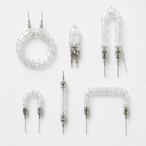
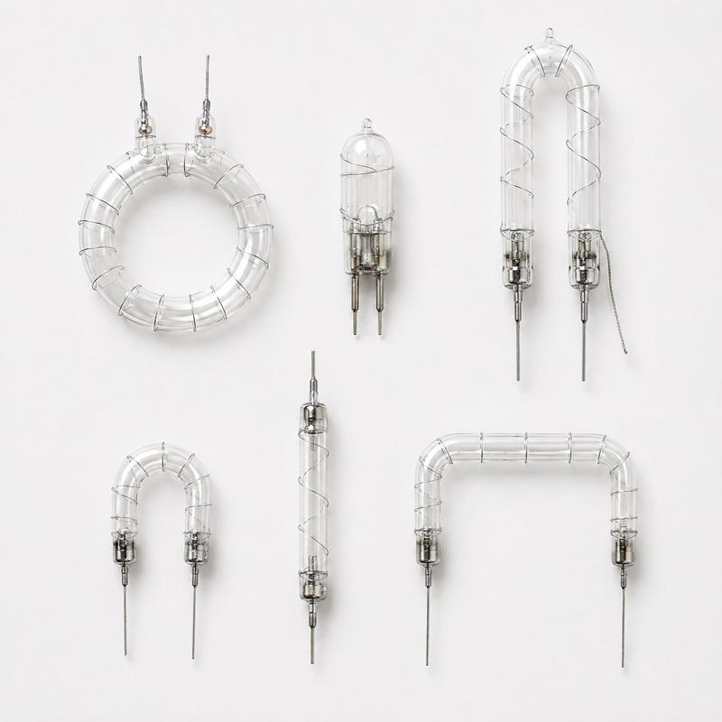
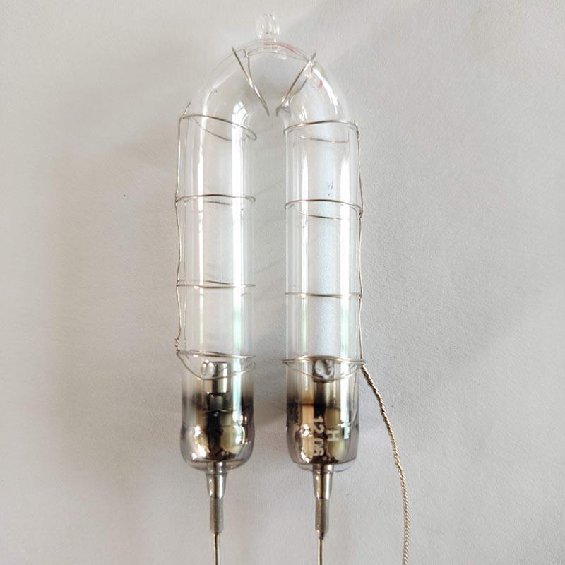
A UV-Vis spectrophotometer xenon flash lamp is suitable only for instruments designed around pulsed xenon illumination. A replacement review must confirm lamp-envelope transmission, arc length and light-center position, optical coupling, stored energy, charging voltage, trigger method, repetition rate and instrument acquisition timing.
STSYSTEMPLC GXEC supports brand-neutral lamp-level matching for laboratory-instrument OEMs, repair centers, distributors and service teams. The original lamp, source module and operating conditions determine the engineering route; a matching label, similar dimensions or one successful flash does not establish compatibility.
Approval should combine drawing or old-sample confirmation with blank-baseline checks, repeated measurements, relevant reference or calibration procedures, thermal operation and a controlled pilot in the intended spectrophotometer.
STSYSTEMPLC GXEC supports pulsed xenon flash lamp matching for UV-Vis spectrophotometers used by laboratory-instrument manufacturers, repair centers, distributors and maintenance teams. The practical question is not whether a lamp can ignite, but whether its useful spectral output, arc position, trigger behavior and pulse stability remain compatible with the instrument optics, wavelength-selection system, detector timing and acceptance method.
A qualified replacement route begins by confirming that the original instrument uses a pulsed xenon source. The original lamp, source module, mechanical dimensions, circuit conditions, optical position and reported symptoms are then compared before an identified sample is installed and tested.
The lamp supplies broadband pulsed optical energy, while the complete measurement chain also includes source optics, a monochromator or filter system, sample compartment, detector, electronics, calibration and software. Stable measurement therefore depends on the instrument as a system, not on the lamp alone.
Historical model, label or old-sample information from Heimann, EG&G, PerkinElmer or Excelitas-era supply contexts may help identify a legacy route. These names describe equipment or supply history only and do not imply affiliation, original-part status or automatic compatibility.
A UV-Vis spectrophotometer xenon flash lamp is a pulsed broadband source for instruments whose optics and electronics are designed around flash illumination. Each pulse enters the source optics and wavelength-selection system, passes through the sample path and is measured by the detector within the instrument’s acquisition cycle.
Replacement suitability is determined by the useful spectral region, spectral transmission of the lamp envelope, arc length and light-center position, stored energy, charging voltage, trigger method, repetition rate, pulse stability, thermal behavior, optical coupling and detector timing. Similar dimensions or a successful first ignition cannot confirm these relationships.
STSYSTEMPLC GXEC provides lamp-level comparison, engineering-sample support and repeat-supply planning. The instrument manufacturer, qualified service provider or laboratory should approve the replacement through its established baseline, repeatability, reference, calibration and performance procedures.
| Engineering Target | What to Confirm | Why It Matters |
|---|---|---|
| Confirmed pulsed-source architecture | Original source module, capacitor-discharge circuit and timed trigger. | Prevents comparison with a continuous arc-lamp architecture. |
| Useful spectral transmission | Required UV and visible region, envelope material, filters and source optics. | Protects usable signal where the instrument actually measures. |
| Arc and light-center position | Arc length, orientation, holder, entrance slit, lens, mirror, fiber or filter position. | Small position changes can alter optical throughput and reference balance. |
| Pulse and trigger compatibility | Capacitor value, charging voltage, stored energy, trigger method, delay and repetition rate. | Connects ignition and pulse shape with detector acquisition. |
| Baseline and signal repeatability | Blank baseline, repeated measurements, warm-up state and reference checks. | Confirms stable behavior in the complete instrument. |
| Controlled repeat supply | Approved sample, drawing, inspection criteria, batch identity and change notification. | Prevents later supply drift after initial approval. |
| Item | What It Covers | What It Does Not Prove |
|---|---|---|
| Pulsed xenon flash lamp | Short broadband pulses in an instrument designed around flash illumination. | Suitability for a continuous xenon arc-lamp instrument. |
| Complete UV-Vis measurement chain | Lamp, optics, wavelength selection, sample, detector, electronics, calibration and software. | That lamp output alone determines wavelength or absorbance accuracy. |
| Legacy replacement route | Old sample, drawing, source-module data, circuit conditions and instrument testing. | Drop-in compatibility based only on a brand, label, appearance or dimensions. |
| Lamp-level endurance evidence | Ignition stability and controlled aging under defined lamp operating conditions. | Complete spectrophotometer accuracy, calibration or universal service life. |
The controlled route is to confirm source architecture, geometry, electrical conditions, optical coupling and acquisition timing, then qualify an identified sample in the intended instrument before regular procurement.
| Parameter | Pulsed Xenon Flash Lamp | LED / LED Array |
|---|---|---|
| Source behavior | Broadband capacitor-discharge pulse in compatible spectrophotometers. | Selected wavelength or multi-LED output controlled by the LED and driver architecture. |
| Spectral route | Useful output is selected by envelope transmission, optics, monochromator or filters and detector response. | Output depends on emitter wavelength, binning, thermal state, optical mixing and driver control. |
| Timing | Trigger delay, pulse shape and acquisition window must match the instrument sequence. | Driver timing, rise/fall behavior and thermal regulation must match the instrument sequence. |
| Replacement boundary | Main risks include arc position, pulse energy, trigger coupling, envelope transmission and duty mismatch. | Main risks include wavelength coverage, driver redesign, optical mixing, thermal margin and recalibration. |
| Approval rule | Use the source architecture specified by the instrument unless a complete optical, electrical, software and calibration redesign is validated. | The same approval rule applies. |
| Validation Path | Engineering Meaning |
|---|---|
| Strict endurance program | A lamp-level endurance program exceeding 1,100 hours under defined operating conditions, focused on ignition stability and controlled aging behavior. |
| Risk-control matching | Geometry, trigger route, pulse energy, repetition rate, temperature and endurance level are reviewed to reduce hidden misfire, blackening and early-life failure risk. |
| Scaling path | Engineering sample, instrument-side verification, pilot quantity, repeat-supply checks and field feedback expose failure modes before regular procurement. |
| Stage | What Should Be Confirmed | Useful Records |
|---|---|---|
| 1. Source identification | Instrument model, pulsed-source architecture, original lamp, source module, optical position and reported symptom. | Manual, labels, photographs, dimensions, old sample and service history. |
| 2. Lamp and module comparison | Envelope transmission, arc and light center, geometry, stored energy, charging, trigger, repetition rate, thermal route and optical coupling. | Drawing, measurement sheet, circuit data, waveform where available and identified sample record. |
| 3. Instrument installation | Mechanical fit, insulation clearance, optical alignment, startup behavior and operation under original enclosure conditions. | Installation photographs, startup observations and hot/cold operating notes. |
| 4. Measurement checks | Blank baseline, repeated measurements, useful output across the required spectral region and normal reference or calibration checks. | Baseline plots, repeatability data, reference results and calibration records. |
| 5. Pilot and repeat supply | Controlled pilot quantity, approved identity, critical dimensions, incoming checks, traceability and change notification. | Retained sample, approved drawing, batch record, inspection criteria and failure feedback. |
| Observed Issue | Possible Causes | Verification Route |
|---|---|---|
| Weak or reduced signal | Lamp aging or blackening, shifted light center, optical contamination, unsuitable envelope transmission, detector deterioration or an electronic fault. | Compare the original lamp with the sample lamp, inspect the optical path, confirm the spectral region and run blank and reference checks. |
| Unstable baseline or repeatability | Pulse-energy variation, trigger delay, thermal drift, optical alignment, acquisition timing or electronic noise. | Repeat blank and reference measurements, compare cold and warm states and review trigger-to-acquisition timing. |
| Intermittent ignition | Electrode aging, weak trigger coupling, charging fault, wiring or insulation damage, or excessive thermal stress. | Check charging voltage, trigger route, connectors, insulation and repeated hot/cold starts; review the waveform where available. |
| Performance changes after warm-up | Seal or electrode temperature, enclosure heat, optical drift or source-module thermal conditions. | Run the normal operating cycle and compare ignition, baseline and signal before and after stabilization. |
| Later batches differ | Uncontrolled material, dimensional or process changes, or missing retained references and incoming checks. | Use an approved drawing, retained sample, batch identity, critical-characteristic inspection and change notification. |
The general xenon flash tube specification supports preliminary discussion of geometry and operating parameters. The RoHS report applies only to the listed models and tested materials. Neither document proves compatibility with a UV-Vis spectrophotometer; approval must also use the actual source-module data, optical path and instrument acceptance method.
| Use | How the Document Supports the Decision |
|---|---|
| Source-module comparison | Provides geometry, trigger and operating references for lamp-level discussion. |
| Instrument acceptance | Combines lamp information with baseline, signal, reference and calibration checks. |
| Legacy supply identification | Uses model numbers, drawings, old samples and equipment data to organize difficult-to-source matching without claiming universal fit. |
| Pilot and repeat procurement | Defines optical, electrical, mechanical, duty-cycle, documentation, quantity and traceability requirements before sample production. |
| Decision Question | Page-Specific Answer |
|---|---|
| Who is this route for? | UV-Vis instrument OEMs, repair centers, distributors, maintenance teams and laboratories managing compatible pulsed-source equipment. |
| Which equipment is suitable? | Spectrophotometers or photometers whose source module is designed for a pulsed xenon flash lamp and whose acceptance method can be reproduced. |
| Which cases need additional evaluation? | Continuous xenon arc-lamp instruments, unknown source architecture, high-energy or high-frequency circuits, regulated equipment and incomplete optical or electrical data. |
| How is matching confirmed? | Through original-lamp or drawing comparison, source-module inspection, electrical review, arc-position and optical-coupling confirmation, and instrument-side testing. |
| How should samples be introduced? | Use identified prototypes, defined measurement checks, a controlled pilot quantity and written approval records. |
| How are long-term spares managed? | Preserve approved samples, drawings, inspection criteria, batch traceability, change notification, annual demand and failure-feedback records. |
| Search Route | Representative Search Intent |
|---|---|
| UV-Vis replacement | UV-Vis spectrophotometer xenon flash lamp replacement, spectrophotometer pulsed xenon lamp and laboratory xenon source. |
| Legacy supply context | Heimann, EG&G, PerkinElmer and Excelitas-era model, label, sample or source-module identification. |
| Measurement context | baseline drift, weak signal, absorbance repeatability, optical alignment and acquisition timing. |
| Procurement context | old sample matching, engineering prototype, approved sample, batch control and long-term spare supply. |
| Item | Buyer Input | Why It Matters |
|---|---|---|
| 1. Instrument and source mode | Instrument brand/model, pulsed or continuous source and intended wavelength region. | Prevents comparison with the wrong xenon source category. |
| 2. Original lamp and geometry | Tube, ruler, electrodes, leads, connector, holder and light-center photographs. | Defines mechanical fit and optical position. |
| 3. Electrical conditions | Capacitor value, charging voltage, trigger method, repetition rate and waveform if available. | Defines the discharge and timing window. |
| 4. Optical and measurement symptoms | Baseline behavior, weak signal, intermittent ignition, spectral behavior and acceptance method. | Connects lamp comparison with instrument performance. |
| 5. Trial and supply plan | Prototype quantity, reference or calibration checks, annual demand and traceability needs. | Defines qualification and repeat-supply control. |
| Review Item | Why It Matters |
|---|---|
| Arc Length and Light Center | Protects coupling into the entrance optics, monochromator, filter system or fiber path. |
| Envelope and Spectral Route | Confirms that the required wavelength region can pass through the lamp and source optics. |
| Trigger Coupling and Acquisition Timing | Controls intermittent ignition and ensures the detector samples the intended part of the pulse. |
| Pulse Energy and Repetition Rate | Defines the electrical and thermal duty window and reduces early blackening or unstable output risk. |
| Baseline and Reference Checks | Separates lamp behavior from optics, detector, electronics and calibration effects. |
| Sample Approval Discipline | Prevents approval based only on ignition, appearance or a single reading. |
| CORE Level | Recommended Use |
|---|---|
| CORE A | For critical laboratory or OEM programs after full lamp, source-module and instrument validation. |
| CORE B | For standard UV-Vis replacement after geometry, electrical, optical and acceptance checks are completed. |
| CORE C | For engineering samples, lower-duty screening or preliminary matching with a narrower evidence window. |
| Question | Answer |
|---|---|
| Can a UV-Vis spectrophotometer xenon lamp be selected by dimensions alone? | No. Source architecture, spectral transmission, arc position, stored energy, trigger method, repetition rate, optical coupling, acquisition timing and instrument acceptance checks must also be considered. |
| How can I identify a pulsed xenon source? | Check the instrument manual, source module, power supply and operating behavior. A pulsed source normally uses capacitor discharge and timed triggering, while a continuous arc source uses a different power architecture. |
| Does a new lamp automatically restore wavelength or absorbance accuracy? | No. Optics, wavelength selection, detector, electronics, calibration, sample handling and software also affect instrument performance. |
| What information is needed when no drawing is available? | Send the original lamp, ruler photographs, source-module and optical-coupling photographs, equipment model, electrical conditions, wavelength region, symptoms, acceptance method and quantity. |
| How should an engineering sample be approved? | Install the identified sample in the intended instrument and use blank-baseline checks, repeated measurements, relevant reference materials and the owner’s normal calibration or performance procedure. |
| Can a historical brand or part number confirm compatibility? | No. It can help identify a supply context, but compatibility still depends on the actual lamp, source module, circuit, optics and instrument-side results. |
A first flash proves ignition; repeatable instrument results prove the replacement route.
| Related Page | Engineering Focus |
|---|---|
| OEM Analytical Instrument Xenon Flash Lamp Source Module | Source-module design inputs, prototype validation, integration boundary and repeat supply. |
| Water Quality Analyzer Xenon Flash Lamp Replacement | UV absorbance, water-side optical conditions, reference checks and controlled pilot. |
| Industrial Stroboscope Xenon Flash Tube | High-repetition discharge, trigger stability, thermal conditions and defined duty cycle. |
| Mobile Speed Camera Xenon Flash Tube | Short-pulse timing, optical position, vibration conditions and equipment-side image acceptance. |
A first flash proves ignition; repeatable instrument results prove the replacement route.
© STSYSTEMPLC GXEC. All rights reserved.

Address : F4,Bldg A, Hanzhong Industrial Park, No.67, North of Xinsha Ave, Xin Tang, Zeng Cheng, Guang Zhou, China
Tel : +86 20 8278 0427
Email : info@stsystemplc.com
Email : morrison426@163.com