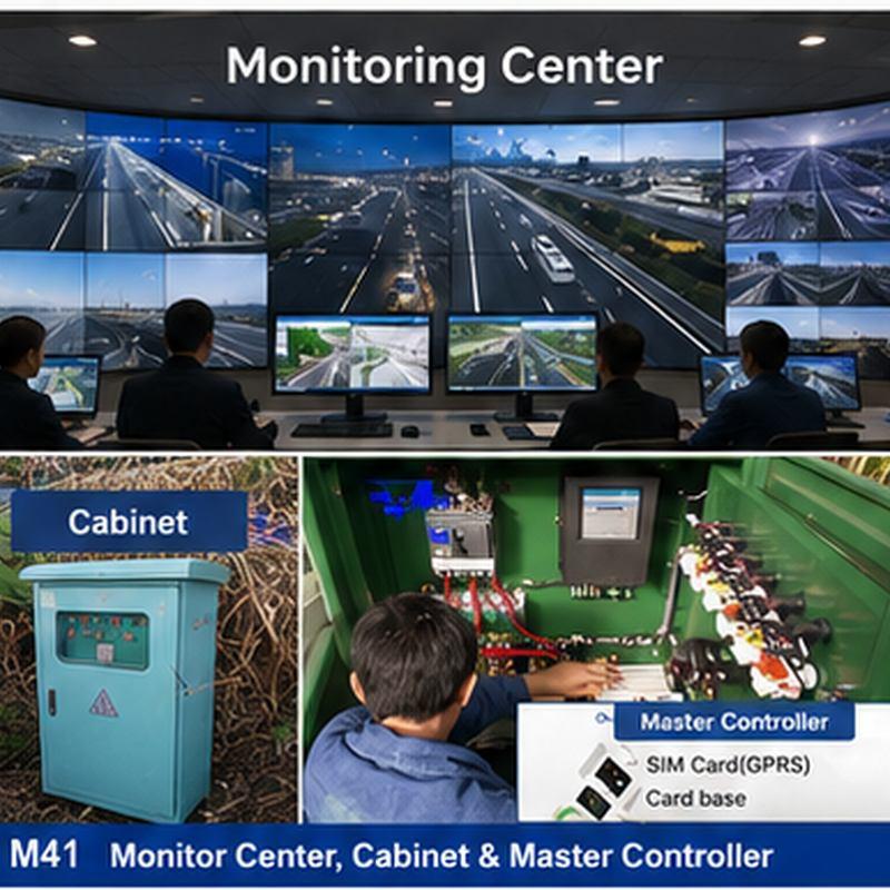
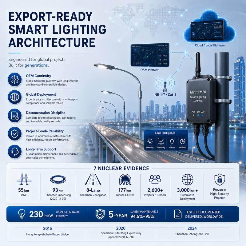

Interconnected Smart Electrical Cabinet Monitoring System for Distribution Panels and Power Rooms Tier 1+ benchmark language: layered ecosystem, cybersecurity-ready deployment boundary, owner-controlled local data and documented integration review are stated without unsupported certification or universal compatibility claims. Integration is defined by point list, protocol mapping, gateway configuration and site acceptance scope.
STSYSTEMPLC defines this page through Interconnected Terminal → System → Operations Center: field terminals, system dashboards and owner-side records for smart electrical cabinet monitoring, cabinet integration, local server options and project-based power-data workflow.
Core search focus: interconnected smart electrical cabinet monitoring system, smart electrical cabinet monitoring, distribution cabinet energy monitoring.
For qualified strategic partners, STSYSTEMPLC can support Partner-Branded Solution Packaging and Owner-Controlled Deployment for Security-Sensitive Infrastructure Projects.
STSYSTEMPLC uses Interconnected as the architecture-level positioning word. This page turns smart electrical cabinet monitoring into a deployable Terminal → System → Operations Center workflow, connecting cabinet-side terminals, system dashboards, local-server options and owner-side operating records without presenting the solution as a loose smart device.
Overview · Google Direct Answer
An Interconnected Smart Electrical Cabinet Monitoring System connects cabinet-mounted power terminals, system dashboards and owner-side operations records. It helps panel builders, facility teams and integrators monitor cabinet circuits, electrical alarms, energy use, switching status and local-server data from one cabinet-to-system-to-operations-center architecture.
Electrical cabinet manufacturers building smart cabinet options
Power rooms that require panel-level alarms and energy records
Facilities that need cabinet data on a local server or dashboard
System integrators combining cabinet devices with BMS or SCADA
Projects without circuit names or cabinet wiring scope
Consumer-grade installations without cabinet-level engineering review
Sites that expect a universal device without configuration
Architecture
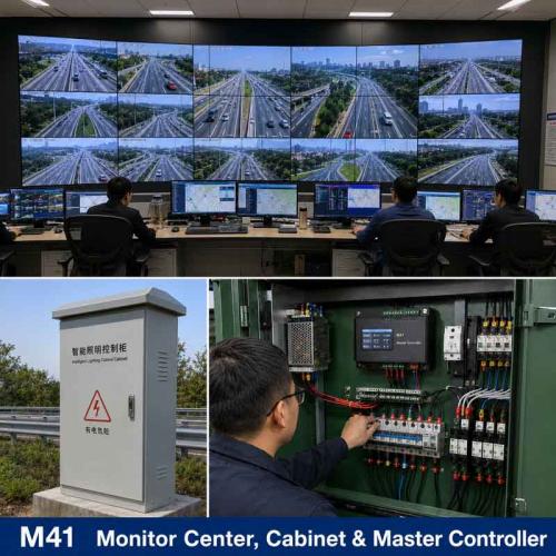
Cabinet-mounted smart power management terminals collect circuit values, load status, event records and selected switching information inside distribution panels or smart electrical cabinets.
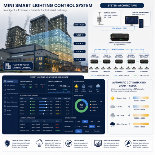
The system layer organizes cabinet data into alarms, circuit dashboards, report fields, permissions and exportable owner records.
The operations center uses local server, monitoring wallboard or facility dashboard to review cabinet status, events and energy visibility across rooms or sites.
Tier 1+ Industrial Benchmark
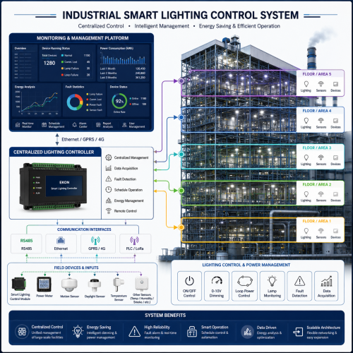
STSYSTEMPLC positions this page as an Interconnected engineering architecture, not as an isolated smart device. The benchmark direction is a layered, open and cybersecurity-ready structure: field terminals, system dashboards, local-server or private-cloud deployment, owner-controlled records and project-based BMS / EMS / SCADA integration.
Use the same industrial logic buyers expect from leading platforms: connected field devices, edge or system control, and owner-side analytics or operations records.
Describe encrypted communication review, role-based access, user permissions, local-server policy and audit-ready event records without claiming IEC 62443 certification unless a valid certificate exists.
Use documented point lists, protocol mapping, gateway interfaces and acceptance-test requirements. Do not claim universal support for OPC UA, MQTT, BACnet/IP, WinCC or EcoStruxure unless confirmed by the project configuration.
Buyer Decision Boundary
Terminal Layer
| Terminal Item | Project Definition | Owner Record |
|---|---|---|
| Circuit identity | Define circuit name, load group, cabinet position and current range before terminal selection. | Prevents treating the terminal as a generic smart component. |
| Electrical values | Confirm voltage, current, energy, selected alarm values and operating conditions. | Creates traceable records for dashboard and maintenance review. |
| Control boundary | Define whether remote switching, contactor linkage or status feedback is required. | Keeps control authority accountable to the owner. |
| Communication path | Confirm RS485, Modbus, gateway, local server, private cloud or customer platform route. | Links terminal data to the interconnected system layer. |
System Layer
Organize events by circuit, cabinet, severity, time, response status and service follow-up.
Convert metered data into period reports, abnormal-load review and owner-readable energy records.
Support data-sovereignty and private-deployment requirements through project-defined local-server or private-cloud scope.
Operations Center
| Owner Need | Operations-Center Function | Practical Output |
|---|---|---|
| Facility safety review | Alarm dashboard, event list and maintenance follow-up status. | Traceable electrical records for owner and service teams. |
| Energy cost visibility | Monthly reports, abnormal consumption review and load comparison. | Better operating decisions based on named circuits and sites. |
| Private deployment | Local server, private cloud, wallboard or controlled user access. | Data stays within the project boundary defined by the owner. |
| Multi-site operations | Site comparison, role permissions and exportable reports. | Headquarters or facility groups can manage many cabinets or sites together. |
Applications
Use the interconnected terminal-to-system-to-operations-center route to keep cabinet data, records and owner decisions connected.
Use the interconnected terminal-to-system-to-operations-center route to keep cabinet data, records and owner decisions connected.
Use the interconnected terminal-to-system-to-operations-center route to keep cabinet data, records and owner decisions connected.
Use the interconnected terminal-to-system-to-operations-center route to keep cabinet data, records and owner decisions connected.
Integration
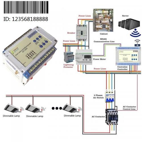
Integration focuses on cabinet installation, RS485 / Modbus communication, gateway data exchange, local server deployment and project-based BMS, EMS or SCADA interface review. Integration should be confirmed through point list, protocol mapping, gateway configuration and site acceptance testing, rather than assumed as universal platform compatibility.
Use documented point lists, protocol routes and acceptance records instead of vague compatibility claims.
Confirm wiring, enclosure, protection devices, installation environment and final assembly scope before certification review.
Use connected smart electrical monitoring language to match mature industry search intent while keeping Interconnected as STSYSTEMPLC positioning.
Required Project Data
| Input Group | Required Information |
|---|---|
| Cabinet scope | Cabinet type, distribution-panel layout, power-room location |
| Circuit definition | Circuit count, circuit names, load groups and current ranges |
| Communication route | RS485 / Modbus / gateway / local server / customer platform |
| Acceptance file | Dashboard fields, alarm records and cabinet-integration review needs |
CE test documentation can support component-level review when the terminal is integrated into smart electrical cabinets. Final cabinet-level conformity depends on the complete enclosure, wiring, protection design, installation environment and destination-market requirements.
Inquiry Guide
Send cabinet type, circuit quantity, voltage, current range, load category, communication path, server preference and required dashboard fields.
No. It is positioned as an interconnected engineering entry that connects field terminals, system logic and owner-side operations records.
Project-based integration can be reviewed according to protocol list, data map, gateway route and site acceptance requirements. Do not assume universal protocol support without confirmation.
CE test documentation can support component-level review when the terminal is integrated into smart electrical cabinets. Final cabinet-level conformity depends on the complete enclosure, wiring, protection design, installation environment and destination-market requirements.
Smart is a search-entry word. Interconnected explains the STSYSTEMPLC architecture: terminals, systems, records, dashboards and operations-center workflow are connected as one project structure.
Send cabinet type, circuit quantity, voltage, current range, load category, communication path, server preference and required dashboard fields.


Address : F4,Bldg A, Hanzhong Industrial Park, No.67, North of Xinsha Ave, Xin Tang, Zeng Cheng, Guang Zhou, China
Tel : +86 20 8278 0427
Email : info@stsystemplc.com
Email : morrison426@163.com