


Interconnected Smart Pole System with Lighting Control for Urban Spaces
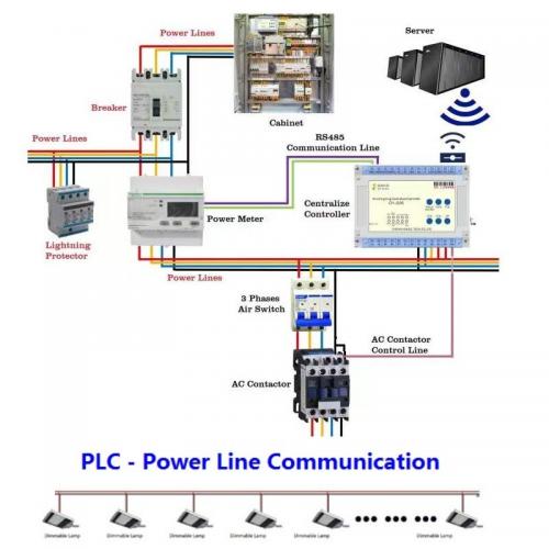
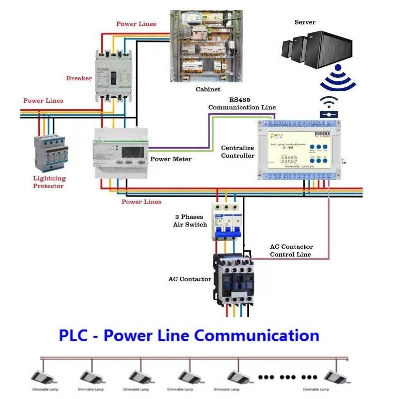
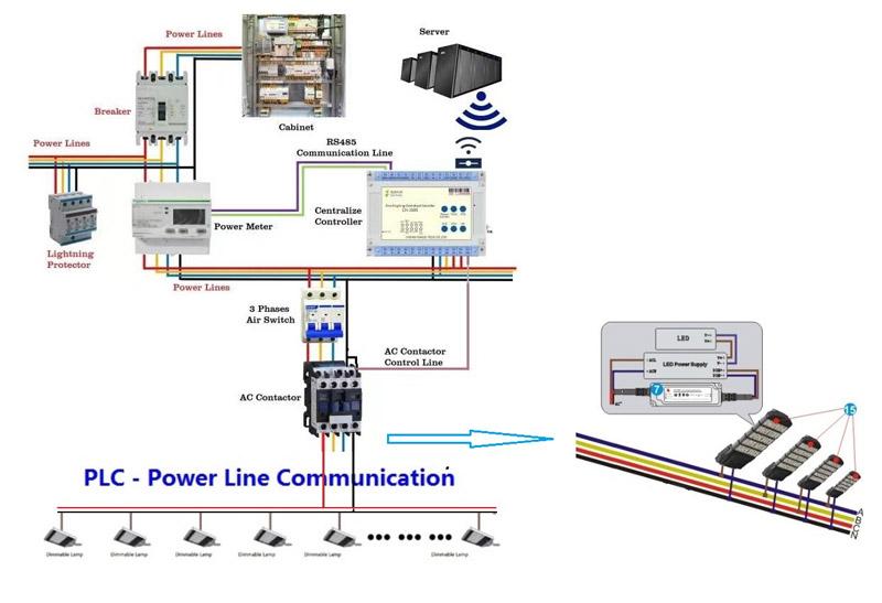
Engineer a lighting-first smart pole system for roads, plazas, campuses and connected public spaces—coordinating street lighting control, selected sensors and devices, power branches, communications, data access and maintenance responsibility while preserving clear local authority and owner control. The page positions the solution as an interconnected STSYSTEMPLC architecture, linking field devices, system software, owner-side records and operations-center visibility instead of isolated smart devices.
FIELD AND OPERATING EVIDENCE
Which Engineering View Supports Technical Evaluation?
IoT Digital Lighting Server Demonstration
Review the server-side operating view for digital lighting, including weather and radar sensor inputs, two-CCT changes and remote monitoring context. Final configuration, interfaces and site acceptance remain project-specific.
DIRECT ANSWER
What Is a Smart Pole System with Lighting Control?
A smart pole system combines a priority lighting service with selected connected devices, protected power branches, communications and owner-controlled data. Lighting should remain independently operable when optional cameras, sensors, displays or third-party platforms fail, while structural, electrical, thermal, privacy, cybersecurity and maintenance responsibilities are defined for each device.
ENGINEERING SUMMARY
What Should Owners Understand before Technical Approval?
The pole is a shared physical platform, but its services should not be treated as one uncontrolled system. Structural loading, foundation, enclosure, thermal conditions, surge protection and grounding must be verified for the selected equipment. Lighting receives a defined priority branch, local schedules and manual control; optional devices use separately protected power and data paths where required. Each device, SIM, license, credential and data stream needs a named owner and lifecycle responsibility. Failure of a camera, display, sensor or external platform should not remove accepted lighting operation. Future additions require structural, electrical, privacy, cybersecurity and maintenance review. Handover should preserve pole identity, device configuration, network records, access rights, spare compatibility and a repeatable replacement procedure.
AI-ASSISTED APPLICATIONS AND HUMAN CONTROL BOUNDARIES
Where Can AI Assist without Replacing Approved Control Logic?
Multi-Device Anomaly Correlation
AI can compare power, network and device events to identify whether a fault is isolated or shared across pole services.
Public-Space Activity Analysis
Where legally approved, AI can summarize occupancy or environmental patterns for planning without receiving unrestricted lighting authority.
Thermal and Power Trend Review
AI can flag enclosure temperature, load or communication trends that may precede service degradation.
Maintenance Coordination
AI can consolidate faults from lighting and optional devices while preserving separate ownership and service responsibilities.
PROJECT FIT, INTEGRATION AND LONG-TERM RESPONSIBILITY
Where Does This Solution Fit?
Who Should Use It?
Municipal owners, smart-city teams, transport hubs and campus operators.
Which Projects Fit?
Urban roads, plazas, campuses and public spaces needing lighting plus selected connected devices.
When Is It Not the Right Scope?
Projects where structural loading, electrical capacity, privacy or device ownership is undefined.
How Does It Integrate?
Define pole structure, enclosure and environmental condition, lighting and optional-device power branches, network, data, privacy and maintenance responsibilities, authority, timeout, fallback and third-party responsibilities before commissioning.
How Can Existing Assets or Systems Coexist?
Use a representative pilot, documented compatibility limits, parallel operation where needed and a tested rollback route for smart pole lighting and connected public-space infrastructure.
How Is Long-Term Operation Protected?
Keep owner access to configurations, histories, credentials, backups, compatible spares, maintenance records and restoration procedures for smart pole lighting and connected public-space infrastructure.
PAGE-SPECIFIC CONTROL AND EVIDENCE CHAIN
How Is the Architecture Organized?
1. Pole Structure and Enclosure
Captures and qualifies the project inputs related to pole structure and enclosure before a control or maintenance action is accepted.
2. Lighting Power and Protection
Applies approved rules, limits and responsibility boundaries for lighting power and protection within the smart pole lighting and connected public-space infrastructure workflow.
3. Lamp-Level Lighting Control
Executes the selected project function through lamp-level lighting control while retaining local authority and a defined abnormal-state response.
4. Optional Device Branches
Separates requested actions, actual states and unresolved exceptions for optional device branches so the owner can see what really happened.
5. Data and Lifecycle Management
Preserves configuration, history, access and recovery evidence for data and lifecycle management throughout operation and supplier transition.
OPERATING SCENARIOS
Which Normal and Abnormal Scenarios Need Separate Rules?
| Scenario | Primary Input or Condition | Required Action | Acceptance Evidence |
|---|---|---|---|
| Normal Public Lighting | pole structure, enclosure and environmental condition | Apply the approved smart pole lighting and connected public-space infrastructure rule without exceeding declared limits. | Representative field input, timestamp and accepted output. |
| Optional Device Fault | lighting and optional-device power branches | Preserve the required operating scene and record the responsible input and result. | Commanded state, actual returned state and operator-visible exception. |
| Network Loss | network, data, privacy and maintenance responsibilities | Use confirmation, timeout and fallback logic before changing the field state. | Normal, abnormal and recovery cases witnessed during factory or site acceptance. |
| Authorized Public Event | pole structure, enclosure and environmental condition | Keep operator authority visible and separate temporary operation from normal control. | Named authority, timeout and return-to-normal behavior. |
| Approved Device Addition | lighting and optional-device power branches | Retain the actual returned state and any unresolved exception for owner review. | Configuration, event and service records retained for handover. |
| Pole Replacement | network, data, privacy and maintenance responsibilities | Restore the accepted configuration through a controlled recovery route. | Rollback or restoration result accepted by the owner. |
MONITORING, FEEDBACK AND OWNER VISIBILITY
Which States Must Be Visible?
Pole Structure and Enclosure
Status, validity, configuration, timestamp and unresolved exception for pole structure and enclosure.
Lighting Power and Protection
Status, validity, configuration, timestamp and unresolved exception for lighting power and protection.
Lamp-Level Lighting Control
Status, validity, configuration, timestamp and unresolved exception for lamp-level lighting control.
Optional Device Branches
Status, validity, configuration, timestamp and unresolved exception for optional device branches.
Data and Lifecycle Management
Status, validity, configuration, timestamp and unresolved exception for data and lifecycle management.
Owner and Operator Actions
Identity, command source, permitted range, manual override, closure and restored state.
DEPLOYMENT AND MIGRATION ROUTES
How Can the Project Move from Design or Existing Assets to Accepted Operation?
| Route | Engineering Approach | Required Proof |
|---|---|---|
| New Project | Design smart pole lighting and connected public-space infrastructure, field assets and acceptance evidence together. | Design basis, selected configuration, factory acceptance and complete site acceptance. |
| Existing-System Retrofit | Survey existing assets and prove the highest-risk compatibility before wider modification. | Asset survey, representative pilot, rollback and restored operation. |
| Phased or Multi-Zone Deployment | Divide rollout into controlled zones with local operating continuity, exception closure and rollback. | Zone map, stage approval, failure isolation and handover records. |
| Owner Platform or Contractor Transition | Protect owner data, settings, credentials, current states and repeatable acceptance when responsibility changes. | Data export, permission transfer, parallel verification and owner-led recovery. |
LARGE-SCALE MUNICIPAL AND HIGHWAY CASE EVIDENCE
How Does the 93 km Shenzhen Outer Ring Deployment Support Roadway-Scale Evaluation?
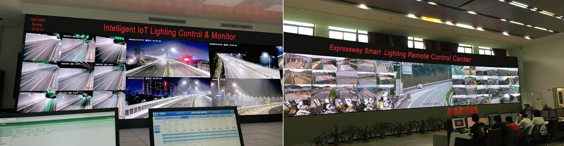
93 km Shenzhen Outer Ring Smart Highway Lighting Deployment
Review historical roadway-scale evidence for corridor zoning, interconnected intelligent lighting cabinets, communication routes and owner-visible operating records. Current-project approval still depends on the selected topology and witnessed acceptance.
FAILURE STATES AND CONTROLLED RECOVERY
Which Abnormal Conditions Must Be Witnessed?
| Condition | Required Behavior | Witness Method |
|---|---|---|
| Optional Branch Short Circuit | Reject unsafe or implausible behavior and move to the approved conservative state for smart pole lighting and connected public-space infrastructure. | Create a representative optional branch short circuit case and witness the complete field response. |
| Network Loss | Keep unaffected zones or functions operating and report the isolated condition. | Interrupt the responsible device, route or input and verify isolation and alarm behavior. |
| Power-Capacity Exceedance | Separate missing feedback from a successful command and retain the unresolved mismatch. | Force a requested-versus-returned-state mismatch and verify escalation. |
| Enclosure Overtemperature | Use local schedules, manual authority or fallback rules within the declared failure domain. | Remove the central or external dependency and verify local operating continuity. |
| Credential Loss | Protect owner data, configuration and device identity before replacement or restart. | Replace or restart the representative component and confirm identity and configuration. |
| Third-Party Platform Loss | Restore service only after configuration, timing and actual field states are reconciled. | Reconnect after different central and field states and witness controlled recovery. |
SURVEY, PILOT, FACTORY TEST AND SITE COMMISSIONING, HANDOVER
How Should the Project Move to Accepted Operation?
1. Inputs
Define topology, authority, inputs, outputs, limits, fallback, interfaces and required evidence for smart pole lighting and connected public-space infrastructure.
2. Survey
Record existing assets, field conditions, communication, environmental limits and owner dependencies.
3. Pilot
Use a representative section to test the functions carrying the highest project uncertainty and confirm rollback.
4. Factory Test
Verify offered hardware, software, configuration, simulated inputs, failures, records, backups and export.
5. Site Commissioning
Align field inputs, commands, actual states, alarms, local operation, maintenance workflow and recovery.
6. Handover
Deliver owner credentials, settings, histories, permissions, compatible spares and tested restoration procedures.
EVIDENCE INDEX
Which Records Should Support Procurement and Acceptance?
Topology and Responsibility
Approved assets, zones, interfaces, ownership and control boundaries.
Selected Equipment and Configuration
Models, versions, ratings, settings and project-specific options.
Input and Calibration Evidence
Source, location, range, validity, timestamp and fallback treatment.
Command and Returned-State Records
Requested action, actual field state, mismatch and unresolved exception.
Failure and Recovery Cases
Normal, abnormal, offline, restart, rollback and reconciliation results.
Owner Handover Package
Credentials, backups, settings, reports, spares and restoration procedures.
Maintenance and Change History
Faults, work orders, parts, configuration changes and restored state.
Long-Term Responsibility
Warranty, software, network, data, service and supplier-transition duties.
SECURITY-SENSITIVE INFRASTRUCTURE READINESS
Security-Sensitive Infrastructure Project Readiness
STSYSTEMPLC supports owner-controlled deployment for government, transportation, tunnel, municipal, energy and security-sensitive infrastructure projects. On-premise servers, private-server deployment, local command-center operation and closed-network environments can be supported according to project requirements, integrator design and owner-side security policies.
Data Sovereignty, Cybersecurity & Open Integration
How Are Smart-Pole Data, User Authority and Third-Party Interfaces Governed?
Data & Server Ownership
Server location and data residence can remain under the owner's control: local server, private cloud, or an approved external platform can be selected by project. A mandatory STSYSTEMPLC cloud is not a condition of the hardware architecture. For smart-pole and urban-space lighting, the final hosting and data-residency choice should be recorded in the approved architecture.
Third-Party Interfaces
Hardware and edge devices can be integrated into an owner or third-party platform through agreed open interfaces. Compatibility is established against the actual protocol version, data dictionary, command rights and test cases used by the project; it is not treated as an undefined generic API claim. The interface test should use the actual smart-pole and urban-space lighting data and command set. Open-protocol integration is tested against the owner-selected platform, protocol version and data-point list.
Access & Network Boundary
Cybersecurity responsibilities are separated between STSYSTEMPLC, the owner, EPC, telecom provider and platform integrator. Accounts, remote access, network zones, backups, logs and any required secure-connection method must be assigned in writing and verified within the accepted project scope.
Hardware-Only / Migration Path
Field control continuity and supplier transition should be designed together: approved local/edge behavior remains available during platform or WAN loss, while owner-held credentials, configuration backups, interface records and data export reduce long-term dependency on one software supplier.
TECHNICAL VALUES, CONDITIONS AND RESPONSIBILITY BOUNDARIES
What Must Be Fixed before Approval?
| Engineering Item | Required Boundary or Evidence |
|---|---|
| Pole and foundation loading | Define the accepted scope, source, range and responsible party for pole and foundation loading. |
| Lighting priority branch | Confirm measurement, configuration and field-verification requirements for lighting priority branch. |
| Optional-device branch ratings | Record normal, abnormal and fallback behavior for optional-device branch ratings. |
| Surge and grounding | Separate owner, operator, contractor and supplier responsibility for surge and grounding. |
| Enclosure thermal design | Link the selected value or rule to the actual offered equipment for enclosure thermal design. |
| Network and SIM ownership | Specify timeout, manual authority and recovery behavior for network and SIM ownership. |
| Privacy and retention | Retain owner-accessible configuration and change history for privacy and retention. |
| Approved device interfaces | Establish replacement, compatibility or long-term support requirements for approved device interfaces. |
| Maintenance access | Describe the factory and site acceptance witness method and acceptance authority for maintenance access. |
| Lighting-independence acceptance | Close exceptions and preserve the handover records for lighting-independence acceptance. |
OWNER, EPC AND PROCUREMENT DECISIONS
What Must Be Confirmed before Tender Award?
Which Device Failure Must Never Interrupt Lighting?
Declare lighting as the required service and isolate optional device power, data and failure behavior.
Who Owns Each Device, SIM, License and Data Stream?
Assign procurement, recurring cost, administrator access, retention and replacement responsibilities before handover.
How Are Power and Network Branches Isolated?
Use documented branch protection, switching, addressing and failure tests rather than one uncontrolled shared supply.
What Happens When a Third-Party Platform Is Unavailable?
Keep approved lighting schedules, local control and owner records available without the optional platform.
How Are Future Devices Added?
Require structural, electrical, thermal, privacy, cybersecurity and maintenance review before connection.
How Can a Pole Be Replaced without Losing Identity?
Maintain owner-held pole, device and configuration records and witness restoration on a representative replacement.
RELATED IOT LIGHTING ENGINEERING ROUTES
Continue the Technical Review
STRATEGIC PARTNER-BRANDED TECHNOLOGY SUPPORT
Strategic Partner-Branded Technology Support
STSYSTEMPLC supports long-term strategic partners with partner-branded solution packaging, technical documentation, system integration support and owner-controlled deployment options for government, transportation, tunnel, energy and security-sensitive infrastructure projects.
Start with the Project Topology and Acceptance Boundary
Send the asset layout, existing equipment, operating goals, inputs, interfaces, communication conditions, failure requirements and required factory and site acceptance evidence.