

Smart Street & Roadway Lighting Control System for Urban Corridors, Highways, Tunnels and Bridges
Connect management platforms, CH-800 edge gateways, intelligent lighting cabinets, circuits, individual lamps and sensors with verified offline local operation.
DIRECT ENGINEERING ANSWER
What Is a Smart Street & Roadway Lighting Control System?
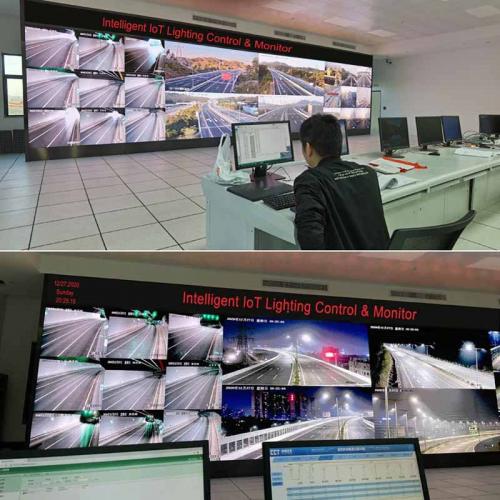
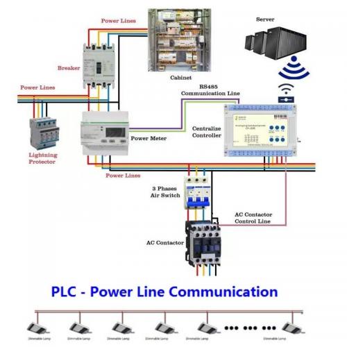
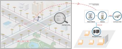
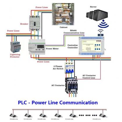
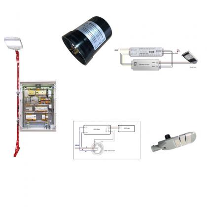
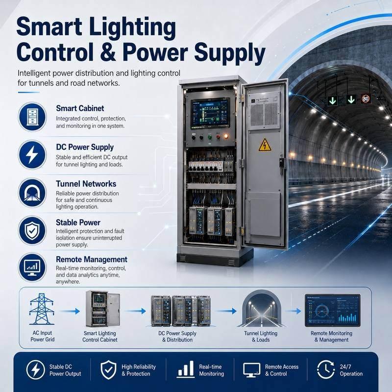
A Smart Street & Roadway Lighting Control System unifies central management platforms, CH-800 edge gateways, intelligent lighting cabinets, circuits, individual luminaires, and traffic or luminance sensors.
It delivers scheduled and adaptive dimming, autonomous local operation during WAN outages, and complete command-versus-state verification across complex urban and highway networks.
PROJECT FIT AND SCOPE BOUNDARIES
Where Does This Control System Fit?
Target Projects
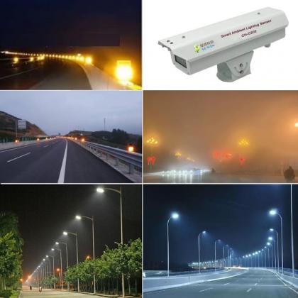
Municipal urban corridors, expressways, municipal tunnels, bridges, and cross-sea infrastructure networks.
System Scope
Cabinet-level switching, group/lamp-level dimming, sensor integration, fault alarms, and energy logging.
Asset Retention
Reuse existing cabinets and luminaires only after compatibility testing and approved rollout verification.
FIELD DEPLOYMENT EVIDENCE
Proven Large-Scale Infrastructure Performance
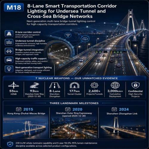
177-Kilometer Expressway Corridor
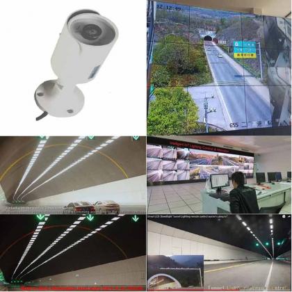
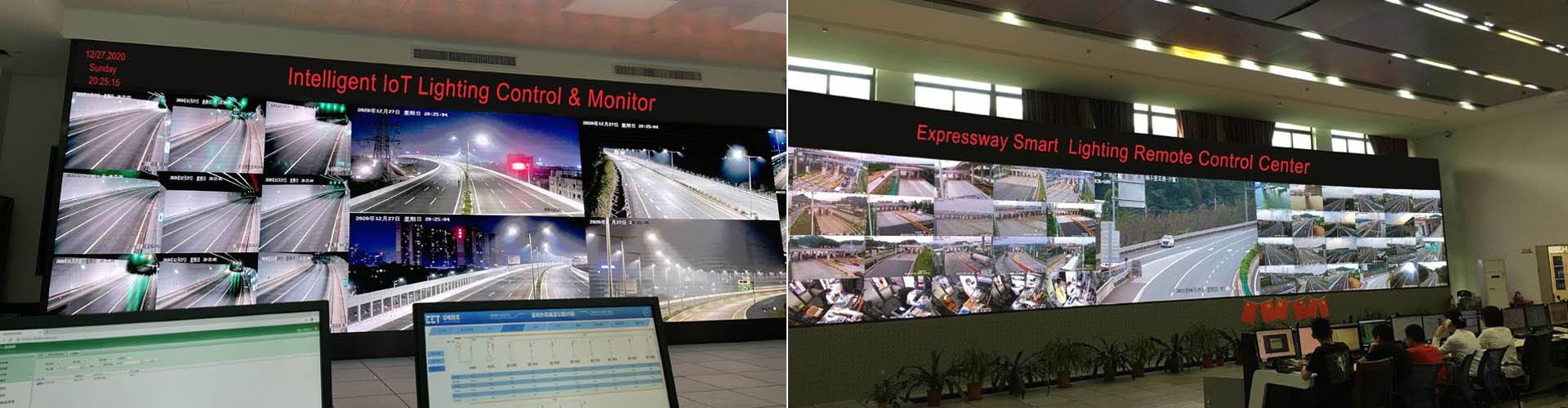
Successfully deployed power-line communication networks and smart terminals across major highway tunnel groups.
93-Kilometer Shenzhen Outer Ring Expressway
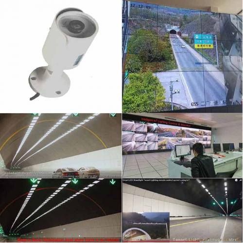
Integrated adaptive CCT and sensor-linked rules for dynamic roadway and tunnel illumination.
SYSTEM ARCHITECTURE
How Is the Control Hierarchy Organized?
1. Central Platform
Manages schedules, user permissions, global analytics, and command logging.
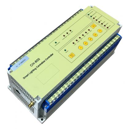
2. CH-800 Edge Gateways
Stores local fallback scenes and executes autonomous zone decisions during network loss.
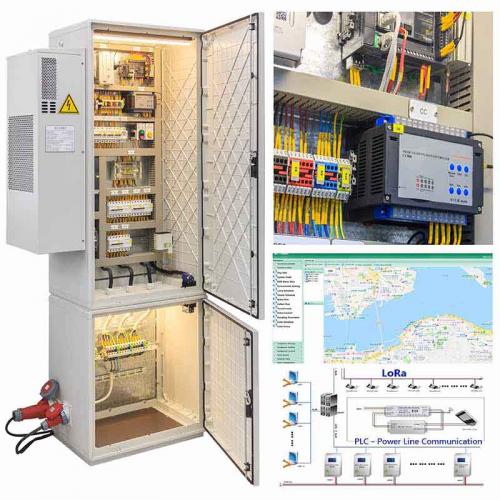
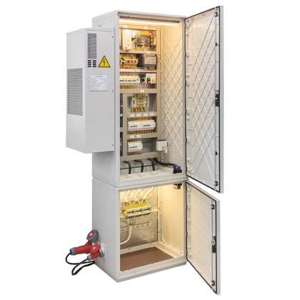
3. Intelligent Cabinets
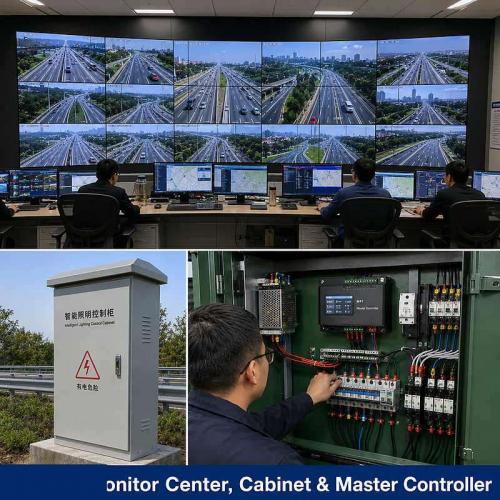
Handles circuit switching, metering, electrical protection, and local cabinet overrides.
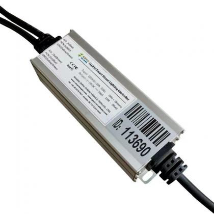
4. Lamp-Level Execution
Delivers precise dimming commands and returns actual operational status and faults.
OPERATING SCENARIOS
Day, Night, Weather, and Outage Scenarios
| Scenario | Primary Inputs | Control Objective |
|---|---|---|
| Normal Nighttime | Astronomical clock or light sensors | Apply scheduled energy-saving dimming levels across roadway circuits. |
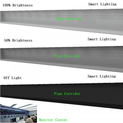
| Weather Intervention | Rain, fog, or snow visibility sensors | Switch to high-penetration CCT and enhanced brightness scenes. |
| WAN / Server Loss | Local edge gateway timer/fallback | Continue safe local schedules and buffer event records for later synchronization. |
MONITORING & STATE FEEDBACK
Complete Visibility from Cabinet to Lamp
Meter Data
Real-time voltage, current, power factor, and cumulative energy consumption.
Circuit Alarms
Instant alerts for cable theft, breaker trips, overvoltage, and power failures.
Lamp Feedback
Individual driver health, operating temperature, and actual dimming level returned.
Audit Logs
Traceable records of all operator commands, overrides, and automated triggers.
COMMUNICATION ROUTES
Flexible Network Topologies
OFDM Power-Line Communication
Utilizes existing power cables for robust command and data transmission without extra wiring.
LoRa Wireless Links
Supports decentralized wireless pole-to-pole connectivity across open highway stretches.
4G / Ethernet Backhaul
Connects edge gateways and intelligent cabinets securely back to the central platform.
DEPLOYMENT ROUTES
Tailored Implementation Options
| Deployment Route | Engineering Fit | Required Validation |
|---|---|---|
| New Infrastructure | Full integration of cabinets, smart poles, sensors, and central software from day one. | End-to-end FAT, simulated faults, and complete SAT commissioning. |
| Lighting Retrofit | Upgrade existing luminaires and cabinets with smart controllers and gateways. | Site asset survey, pilot testing, and verified rollback procedures. |
FAILURE AND RECOVERY
Robust Fallback and Safe Recovery
Offline Autonomy
When cloud servers or network links fail, edge gateways maintain local lighting schedules independently.
Controlled Reconnection
Upon network restoration, historical logs synchronize smoothly without abrupt lighting flickers or state clashes.
FAT / SAT ACCEPTANCE
Structured Verification Workflow
Audit existing electrical lines, cabinet specs, and luminaire parameters.
Validate core lighting control logic on a representative sub-section.
Test software logic, simulated sensor inputs, and gateway failure modes.
Verify live field execution, lighting levels, alarms, and manual overrides.
TECHNICAL VALUES & LIMITS
Core Engineering Specifications
| Parameter | Engineering Specification |
|---|---|
| Operating Voltage | AC 85V – 305V standard grid compatibility. |
| Communication Range | Up to 1000m node spacing for wireless/PLC topologies. |
| Offline Retention | Local edge controllers store schedules and buffer logs indefinitely during outages. |
OWNER DECISIONS
Key Checklist Items Before Tender Award
What fallback scenes operate during server outages?
Ensure local edge gateways are programmed with approved default dimming profiles.
Are maintenance permissions clearly separated?
Define tiered access rights for system administrators, local operators, and field technicians.
RELATED ENGINEERING LINKS
Explore Related STSYSTEMPLC Systems
Ready to Upgrade Your Roadway & Tunnel Lighting Control?
Submit your project layout, pole counts, cabinet locations, and technical requirements for a complete engineering review.