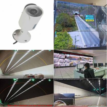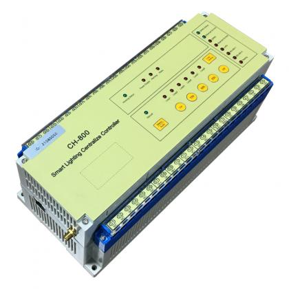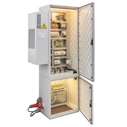

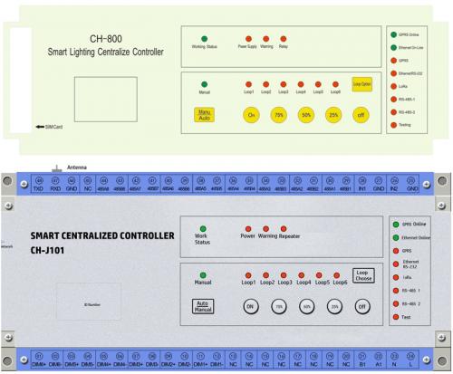
The CH-L0101 loop controller is independently developed by our company. Aimed for industry lighting for warehouse and factory, buildings,stations, and the smart tunnel lighting control system, etc., to control the power supply of lighting fixtures through a human-machine interface, to collect data and monitor the status of the power supply loop.
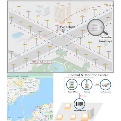
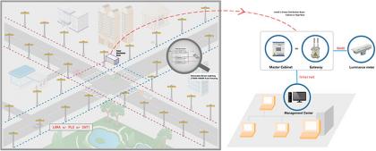
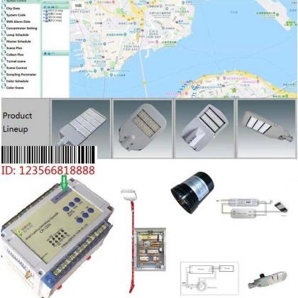
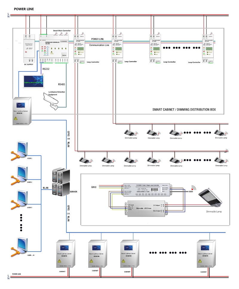
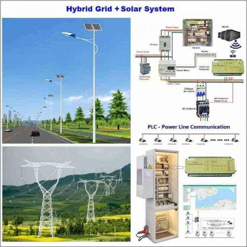
The most advantaged for the Loop Dimming System is to save lot of individual lamp controller on every lighting fixtures, just adjust all of the lamps' brightness by the Centralized Controlling Power Supply Box, the distribution cabinent can also linkage with the Motion Sensor or illuminance sensor to warranty the most effectitve power saving management.
Brand:
SOWINItem NO.:
CH-L0101Order(MOQ):
1Payment:
T/TProduct Origin:
ChinaColor:
GrayLead Time:
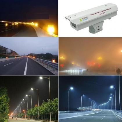
3 weeks6000K ~ 2700K CCT Automatic - Changing at Rainy / Snowing / Foggy Time.
Smart Street Lighting is the key of smart city which standing future of Intelligent Street Lighting.
I: Specification
The CH-L0101 loop controller is independently developed by our company. Aimed for industry lighting for warehouse and factory, buildings,stations, and the smart tunnel lighting control system, etc., to control the power supply of lighting fixtures through a human-machine interface, to collect data and monitor the status of the power supply loop.
The management of traditional lighting fixtures in factories, warehouses, buildings, and stations mostly adopts special personnel manual control and special personnel inspection status, which not only takes up a lot of manpower and material resources, but also has problems such as inadequate management and untimely management. For example, special personnel are required to switch lights every day, Even if time-space equipment such as time controllers and theodolites are used, it still cannot solve multi-time management, abnormal weather operations such as cloudy days, accidents and other incidents, and equipment operations on site are still required. Another example: rigid control methods, lighting scenes, only relying on personnel inspections to find faulty equipment, and unable to provide managers with timely and reliable operating data. In response to these problems, our company has launched this lighting control equipment that integrates data collection, fault monitoring, data processing, local manual control, remote control, automatic operation by settings, theodolite, and sensor linkage.
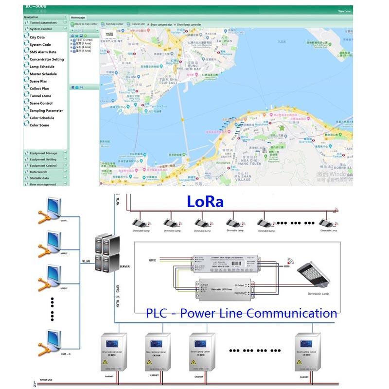
The equipment adopts RS-485 or LoRa communication method, the distance can reach 2000 meters in the open environment without repeater; the communication distance can reach 10,000 meters in the case of repeaters. At most, the equipment has single circuit power supply on-off control, each loop control current up to 30 A( resistive load).
II: PARAMETER
|
Item |
Rating |
|
Working Voltage |
AC 220V±20% or DC 12V |
|
Working Frequency |
50Hz |
|
Static Power |
<5W |
|
Digital Output Loop Quantity(Max.) |
1 Loop |
|
Control Current Per Loop(Resistive Load) |
30A(MAX) |
|
Insulation |
4KV |
|
Power Surge(L-N L-PE N-PE) |
±4KV |
|
Normal Working Temperature |
-25℃ ~ + 60℃ |
|
Limited Working Temperature |
-40℃ ~ + 65℃ |
|
Storage and Transportation Temp.Range |
-45℃ ~ + 65℃ |
|
Storage and Working Humidity Range |
≤85% |
III: FUNCTIONS SPECIFICATION
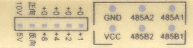
1. Upper Terminal Description
|
N/M |
Marks |
Function |
|
01 |
10V/5V |
Maximum Dimming Voltage Selection |
|
02 |
Forward/ Reverse |
Dimming Direction Selection |
|
03 |
+0/+8,+4,+2,+1 |
Group selection, all 0 is the 16th group. |
|
04 |
GND |
DC power supply Negative |
|
05 |
VCC |
DC power supply Positive |
|
06 |
485A2 |
RS485-2 Communication Interface A |
|
07 |
485B2 |
RS485-2 Communication Interface B |
|
08 |
485A1 |
RS485-1 Communication Interface A |
|
09 |
485B1 |
RS485-1 communication interface B |
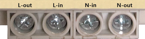
2. Lower terminal description
|
N/M |
Mark |
Function |
|
01 |
L-out |
Equipment Power Supply Live Input (AC Power) Loop Power Live Input |
|
02 |
L-in |
Loop Power Live Output |
|
03 |
N-in |
Equipment Power Supply Neutral Input (AC) Loop power Neutral Input |
|
04 |
N-out |
Loop power Neutral Output |
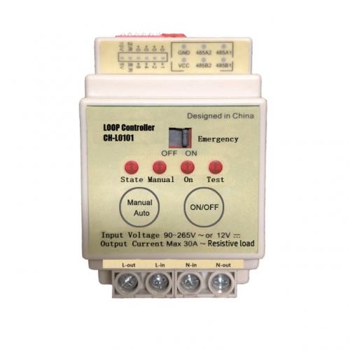
3. Indicator light

|
N/M |
Indicator |
Functions Spec. |
|
01 |
Status |
Device is working normally-Light on Failure-Flashes once in 0.2 seconds If not fault condition, it turns off for 0.5 seconds and then lights up again when the communication data is received. |
|
02 |
Manual |
Light Up-manual state/ Light Off -automatic state. |
|
03 |
ON |
Relay is closed (dimming value is not 0%) lights up, Lights Off when Relay Disconnect (dimming value is 0%). |
|
04 |
TEST |
Reserved |
4. Button Description

|
N/M |
Button |
Specification |
|
01 |
Manual/Auto |
Manual /Auto State switch button, press it to achieve Manual and Automatic state changing |
|
02 |
ON/OFF |
When it is under the Manual State: press this button to switch the loop state, that is say: to switch between closed and open state. |
|
03 |
OFF/ON/EMERGENCY |
When the circuit switch hardware fails, the relay can be opened and closed directly. |
5. Loop power On/Off Control Function
1). Control Priority Level
High priority or Same Level can change the state of low priority or same level, while low priority can not change the state of high priority.
The control mode corresponds to the following priorities.
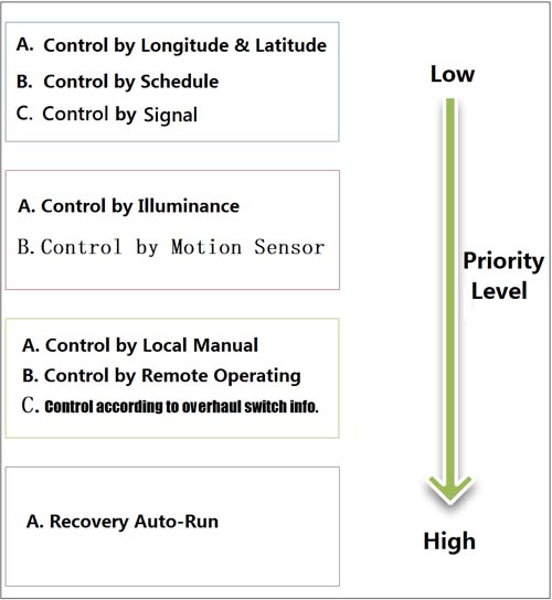
2). Recovery Auto-Run Operating, Priority Level 1 (Highest Priority Level)
At this time, the state of priority Level 4 is executed regardless of the control state in which it was previously operated(the specific operation is performed according to the setting value at the time of installation).
a) The server or client remotely issues “Recovery Auto-Run” command.
b) Press the "Manual/Auto - Run" Button on the device panel
c) The overhaul switch issued "Recovery Auto-Run".
3). Local Manual Control, Priority Level 2
Change the On-Off state of the loop through the loop button on the panel.; at this time, the control commands of priority 3 and priority 4 will not be executed if the manual command is executed.
4). Remote Operation Control, Priority Level 2
Remotely issue the control loop ON/OFF Commands through the Server or the Client ; at this time, the controlled loop will execute the manual command, and the control status of priority 3 and priority 4 will not be executed.
5). Overhaul Switch control (non-standard, need to be customized), Priority Level2
Issued the control loop on-off command through the Overhaul Switch; at this time, all loops will execute manual commands, and the control states of priority 3 and priority 4 will not be executed.
6). Illumination control (non-standard features, need to be customized), priority Level 3
By receiving the illumination value, all loop on-off states are controlled; if there is no illumination value refresh within 30 minutes, the automatic running state is restored (this function is not standard configuration); if the illumination value is continuously refreshed, the control state of priority 4 will not be executed. Running this state needs to be set.
7). Priority Level 3-- Motion sensor control (non-standard features, need to be customized).
Receive the moving state, control all loop conduction, delay a certain time to restore the automatic state, running this state needs to be set.
8). Priority Level 4 -- Latitude & longitude Control
Calculate the sunrise and sunset time through the set latitude and longitude values, the sunrise time will disconnect the loop, and the sunset time will close the loop. The on-off time can be fine-tuned by the sunrise and sunset offset time, the fine-tuning range is 30 minutes.
For priority 3 and 4 states, only one of the states can be executed, which one needs to be set when the equipment is installed, and can also be changed later.
9). Priority Level 4 -- Schedule Control
Through the set 6-segment timetable and on-off status, to control loop on / off.
For priority 3 and 4 states, only one of the states can be executed, which one needs to be set when the equipment is installed, and can also be changed later.
10). Priority Level 4 -- Signal Control (non-standard features, need to be customized)
When the control function is set to Signal control mode, the signal control function is effective;
When the Signal Control is disconnected, the controlled loop power supply is disconnected; when the Signal Control value is closed, the controlled loop power supply is closed.
For priority 3 and 4 states, only one of the states can be executed, which one needs to be set when the equipment is installed, and can also be changed later.
6. Data Collection
Remotely or locally Read the loop status and Digital input port status collected by the device.
7. Electricity Consumption Metering
Internal integration of single-phase electric energy metering module to collect and record the power consumption of electrical equipment in the circuit.
8. Electric Parameter Collection
Collect and record the voltage, current, and active power of the power supply Circuit.
9. Fault Report
Detect the Input and Output status of the power loop. When the output status of the loop power supply does not match the device control status, the power loop power supply failure is determined and reported to the human-machine interface device; for example: the loop device control status is closed, but the loop input If the line is abnormally disconnected, the device will detect an abnormal output, loop fault will be reported by the device at this time.
10. Lamp Dimming
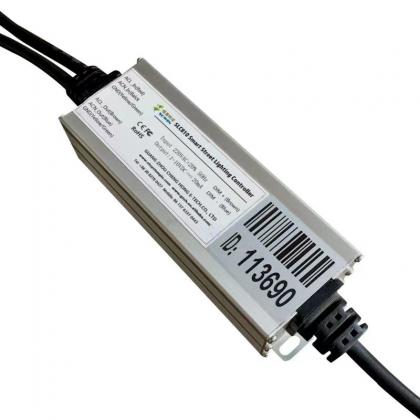
With our loop dimming controller, it can control the brightness of the lamps and achieve the purpose of energy saving.
11. Emergency Operation Function
In the case of failures such as the control bus or the centralized controller, the state of the loop can be manually controlled locally through the switch button on the panel.
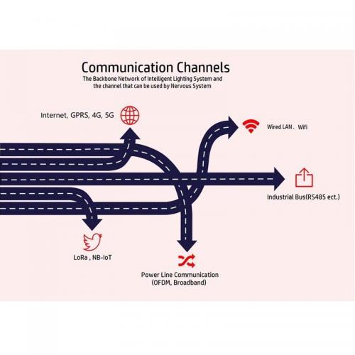
12. LoRa Wireless Communication Function
Through the LoRa communication channel, data exchange and control command reception between the device and the man-machine interface device are realized.
Technical - Advantage are as follows:
a). Adopting the latest international IoT LoRa communication technology , and self-organizing network technology, the communication distance, reliability and safety are greatly improved.
b). The point-to-point communication distance in an open area is up to 2000m, and the measured average in the power plant is up to 1000m.
C). In the case of repeater, the measured 13000m normal communication.
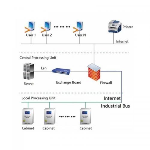
13. RS-485 Communication Function
Through the RS-485 communication channel, data exchange and control command reception between the device and the man-machine interface device are realized.
Technical - Advantage are as follows:
a) The device capacity in the gateway reaches 255.
b) Strong anti-interference, differential mode communication mode, with software fault tolerance, no need to use a dedicated RS-485 communication line, under the premise of ensuring reliability, reducing engineering costs.
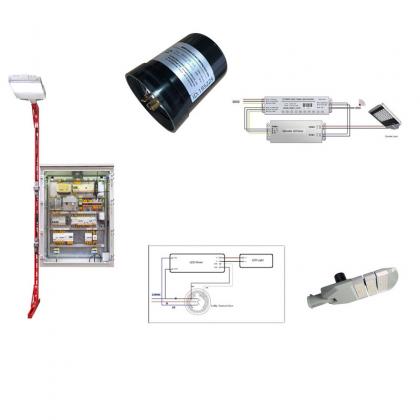
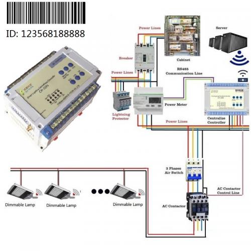
14. Linkage function with AC Contactor
Three-phase power supply is required in special areas (such as street lamps), which can be controlled with 3 p or 4 p AC contactors.
15. Extended function (non-standard)
A) Linkage Function
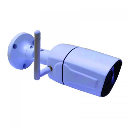
The equipment can be linked with the equipment outside the lighting system such as camera, conveyor belt and so on; for example: the conveyor belt starts, the power supply circuit of the corresponding lighting area of the conveyor belt is closed, and the lighting of the area is replenished.
B) Loop Expansion Function
The control loop can be cascaded.
IV: INSTALLING DIMENSIONS
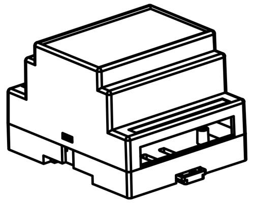
1. 54mm*87.5mm*58.7mm ± 1mm
2. This equipment can be installed with standard rails.
V: Wiring Instructions
1. L-in and N-in are power supply lines, 220VAC. L-out, N-out are connected to the power supply cord of the controlled device.
2. There are two 485 terminal blocks, the wire sequence is the same, and the next device of the same type can be cascaded.
3. In the design, 485-2 is connected to the centralized controller, and 485-1 can be connected to the loop dimming controller.
Application examples
1. Local Manual Switch On/Off
1) Manual automatic state setting
Observe the Manual-Auto indicator light, if the indicator light is on, it means it is running in the manual state -- no operation is required; otherwise, press the "manual-auto" button, and the manual automatic indicator light will light up and enter the manual state;
2) Opening and closing
In the manual state, press the "on/off light" button, the on and off states will be switched in sequence. When the "light on" indicator light is on, it is in the closed state.
Related Tags :


Address : F4,Bldg A, Hanzhong Industrial Park, No.67, North of Xinsha Ave, Xin Tang, Zeng Cheng, Guang Zhou, China
Tel : +86 20 8278 0427
Email : info@stsystemplc.com
Email : morrison426@163.com