

Human-Centric Adaptive Tunnel Lighting for Black-Hole and White-Hole Mitigation, Visual Adaptation and Entrance-Exit Safety
Build the project around Tunnel Lighting, Tunnel Lighting System, Tunnel Lighting Control System and Adaptive Tunnel Lighting with direction-specific zone curves, local continuity, manual authority and owner-readable acceptance evidence.
TUNNEL LIGHTING SOLUTION VIDEO
Adaptive Tunnel Lighting System, Portal Control and Visual Transition
Tunnel Lighting Control from Portal Sensing to Local Execution
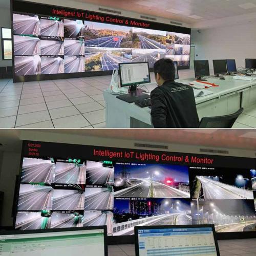
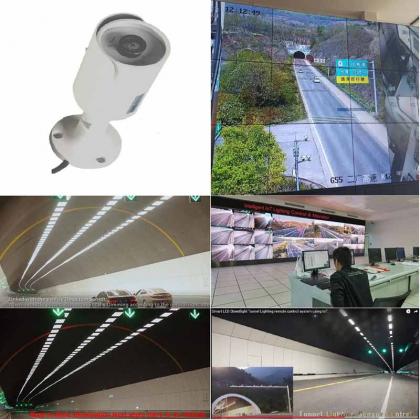
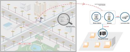
Review the relationship between tunnel zones, portal luminance, adaptive lighting curves, intelligent cabinets, edge control, circuit or lamp-level execution and operator-visible states. Project approval still depends on the offered topology, configured limits and witnessed FAT/SAT evidence.
DIRECT ENGINEERING ANSWER
What Is a Tunnel Lighting System with Adaptive Control?
A Tunnel Lighting System coordinates portal luminance sensing, traffic inputs, approved lighting curves, intelligent lighting cabinets, circuits and lamp-level execution across approach, threshold, transition, interior and exit zones.
A Tunnel Lighting Control System should not react to one uncontrolled sensor value. It validates exterior luminance, traffic and equipment states, selects an approved zone curve, applies declared ramp rates, preserves minimum scenes and retains manual authority and actual returned states.
Black-hole and white-hole mitigation depends on the complete visual-transition design: portal orientation, exterior luminance, tunnel geometry, pavement, luminaire optics, design speed, zone length, dimming curve and verified field measurements.
PROJECT FIT, INTEGRATION AND RESPONSIBILITY
Where Does This Adaptive Tunnel Lighting Solution Fit?
Who Should Use It?
Highway authorities, tunnel operators, design institutes, electromechanical EPC teams, lighting designers and long-term operation and maintenance teams.
Which Projects Fit?
Highway, mountain, urban, subsea and long tunnels where portal luminance, traffic, weather or operating modes require coordinated zone control.
When Is It Not the Right Scope?
Short, low-speed tunnels where a verified fixed scene already meets the required visual and operating criteria and networked adaptation adds no justified value.
How Does It Integrate?
Define sensing, power, communication, zone ownership, command priority, manual control, timeout, fallback and third-party interfaces before commissioning.
How Can Existing Assets Be Retained?
Survey cabinets, circuits, luminaires, drivers, sensors and communication routes. Reuse only assets qualified through compatibility tests and a documented rollback route.
How Is Long-Term Operation Protected?
Keep owner access to zone curves, permissions, calibration records, configurations, alarms, backups, compatible spares and tested restoration procedures.
FIELD EVIDENCE FOR HIGHWAY AND TUNNEL PROJECTS
Which Operating Views Support Technical Evaluation?
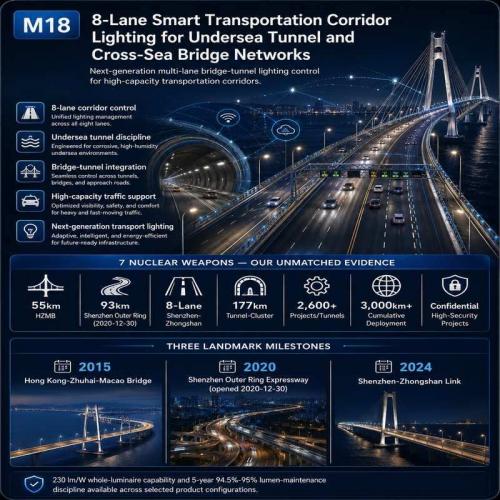
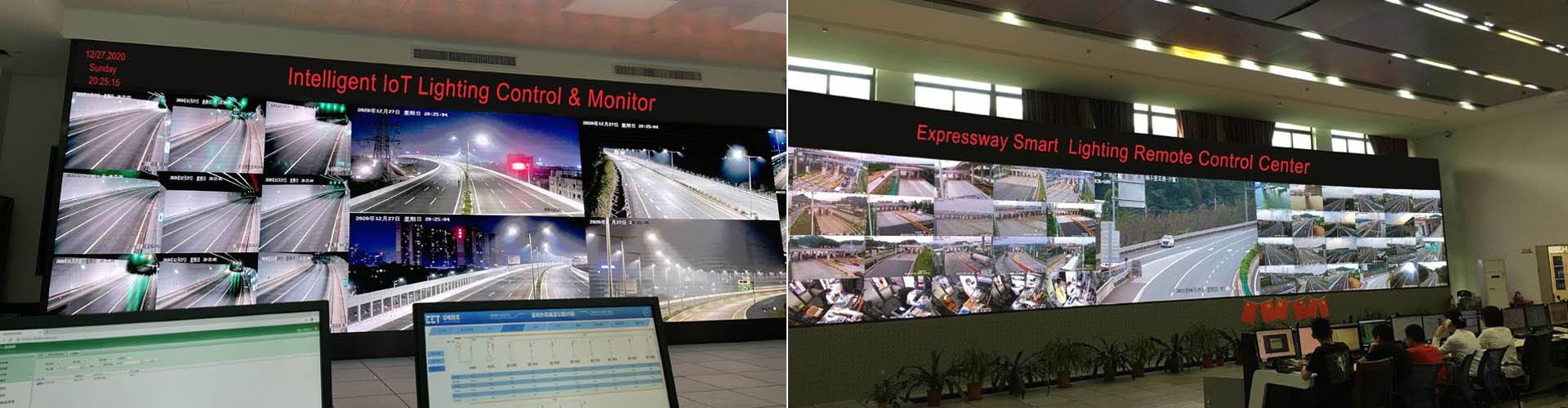
93 km Smart Highway and Tunnel Lighting Deployment
Review corridor zoning, intelligent cabinets, communication routes and the relationship between roadway, portal and tunnel lighting operations.
Adaptive CCT under Rain, Fog and Snow Conditions
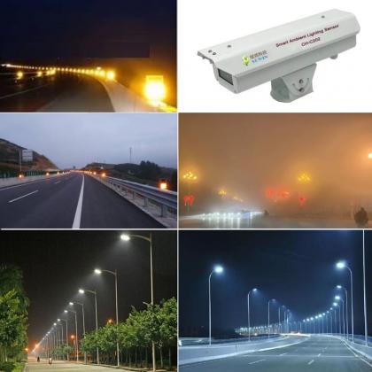
Review how project-configured CCT scenes can be coordinated with measured conditions, local authority and approved transition rules.
BLACK-HOLE, WHITE-HOLE AND VISUAL ADAPTATION LOGIC
How Should the System Support Driver Visual Adaptation?
Exterior Condition
Measure the relevant portal luminance and operating context from an approved location instead of using a generic daylight value.
Direction-Specific Design
Evaluate each driving direction separately because portal orientation, sunlight, geometry and traffic approach are not automatically identical.
Controlled Transition
Use approved zone curves and ramp rates so output changes are gradual, traceable and consistent with the visual-transition design.
Verified Minimum Scene
Preserve the approved minimum operating scene during sensor, network or platform abnormalities until the condition is resolved.
APPROACH, PORTAL AND INTERIOR ZONES
How Should Tunnel Lighting Zones Be Separated?
| Zone | Primary Engineering Objective | Items to Confirm | Required Evidence |
|---|---|---|---|
| Approach Zone | Establish the exterior visual and traffic conditions before the portal. | Measurement position, portal orientation, design speed, weather influence and pre-detection distance. | Sensor layout, calibration record, direction-specific test and data plausibility cases. |
| Threshold Zone | Support initial adaptation when entering from a bright exterior environment. | Required luminance, zone length, luminaire distribution, glare control, curve selection and minimum scene. | Lighting calculation, photometry, field measurement and command-versus-state record. |
| Transition Zone | Reduce output through an approved gradual curve instead of an abrupt change. | Step or continuous dimming, ramp rate, spacing, returned states and exception handling. | Timed transition test, measured output and controller feedback. |
| Interior Zone | Maintain the approved scene for traffic, maintenance and abnormal conditions. | Traffic influence, scheduled scenes, local control, circuit separation and outage behavior. | Day, night, maintenance and communication-loss cases. |
| Exit Zone | Support adaptation when leaving under project-specific exterior conditions. | Direction-specific design, exterior condition, evening or night operation and separate acceptance cases. | Direction-specific measurements and witnessed scene transitions. |
TUNNEL LIGHTING CONTROL AND EVIDENCE CHAIN
How Is the Adaptive Control Architecture Organized?
1. Portal Luminance and Traffic Sensing
Measures exterior luminance, traffic direction, speed and operating conditions before selecting an approved portal lighting curve.
2. Zone-Curve and CCT Policy
Coordinates approach, threshold, transition, interior and exit-zone output, including approved ramp rates, minimum scenes and project-configured CCT.
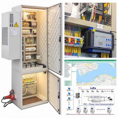
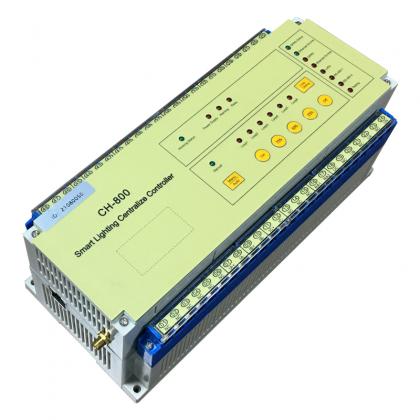
3. CH-800 Edge Gateway and Cabinet
Stores approved local schedules and safety scenes, executes zone-level decisions and preserves defined operation during central-platform or WAN loss.
4. Circuit and Lamp-Level Execution
Delivers group or lamp-level dimming commands, verifies actual operating states and reports circuit, driver, communication and lamp exceptions.
5. Returned-State Records and Manual Authority
Records commands, actual field states, alarms, timestamps and user actions while preserving approved manual override and recovery authority.
DAY, NIGHT, WEATHER AND OPERATING SCENARIOS
Which Scenarios Need Separate Rules and Acceptance Cases?
| Scenario | Primary Inputs | Control Objective | Acceptance Focus |
|---|---|---|---|
| Bright Sunny Portal | Exterior luminance, direction, traffic and equipment status. | Select an approved higher portal curve while preserving glare and ramp limits. | Threshold output, transition timing, returned states and manual authority. |
| Cloudy or Rapidly Changing Light | Validated luminance trend and confirmation time. | Avoid unnecessary repeated scene changes and unstable dimming. | Hysteresis, confirmation time and no uncontrolled oscillation. |
| Rain, Fog or Snow | Weather input, visibility context and project-approved CCT policy. | Apply the approved scene and CCT only within the selected luminaire and owner policy. | CCT range, output, transition behavior and fallback. |
| Night Operation | Time, exterior condition, traffic and owner schedule. | Maintain the verified night scene without copying daytime portal logic. | Minimum scene, traffic influence and energy records. |
| Maintenance Mode | Authorized operator command and work-zone information. | Preserve local manual authority and clearly separate maintenance scenes from automatic operation. | Permissions, status indication, timeout and return to normal operation. |
| Platform or WAN Loss | Local schedules, last approved configuration and field states. | Continue approved local operation and buffer records for later reconciliation. | Offline duration, state continuity, timestamps and controlled synchronization. |
MEASUREMENT, FEEDBACK AND RECONCILIATION
Which States Must the Owner See and Compare?
Portal Sensors
Current value, validity, calibration status, stale-data condition and selected fallback.
Traffic Inputs
Direction, speed or traffic state, confidence, timeout and permitted influence on scenes.
Grid and Cabinet
Supply events, meter data, cabinet status, gateway state and local-control mode where included.
Circuits
Switching, dimming, load, abnormal condition and unresolved circuit alarm.
Lamps and Drivers
Commanded level, returned state, communication, driver or sensor data supported by the selected controller.
Operator Actions
User identity, command source, timestamp, approved range, manual override and recovery result.
COMMUNICATION ROUTES AND EDGE CONTINUITY
How Should Communication Support Tunnel Lighting without Becoming a Single Failure Point?
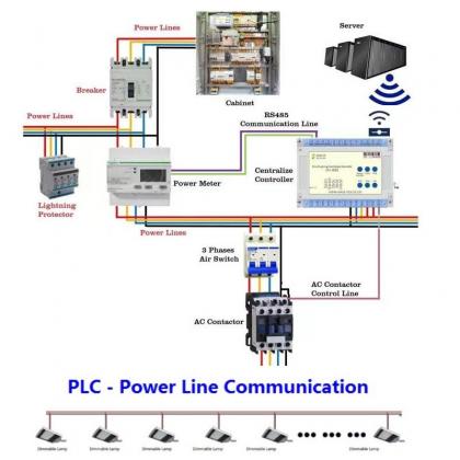
OFDM PLC
Can use suitable power conductors for command and feedback where feeder topology and measured electrical noise support the selected design.
LoRA
Can support selected wireless links where path, antenna position, obstruction, local spectrum rules and owner network policy are confirmed.
Cellular or Ethernet
Can connect approved edge or central routes where coverage, cybersecurity, ownership, recurring service and recovery responsibilities are defined.
Local Edge Operation
Approved schedules and safety scenes remain inside clearly defined zones so central connectivity is not required for every field action.
DEPLOYMENT ROUTES AND REQUIRED PROOF
Which Route Fits the Existing Assets and Project Risk?
| Deployment Route | Project Fit | Required Proof |
|---|---|---|
| New Tunnel | Design sensing, zones, cabinet and circuit boundaries, communication, local fallback and acceptance as one coordinated system. | Design calculation, cabinet and controller FAT, simulated input tests, field calibration and complete SAT. |
| Existing Tunnel Retrofit | Retain qualified cabinets, circuits, luminaires or drivers only after survey and representative compatibility testing. | Asset survey, electrical and communication records, pilot, rollback method and witnessed recovery. |
| Long Tunnel or Tunnel Cluster | Segment control and communication into defined edge zones to limit failure propagation and preserve local operation. | Zone map, gateway and cabinet failure tests, route-quality records and offline-duration verification. |
| Bridge-Tunnel Corridor | Use one management platform while preserving separate rules for roadway, portal, transition and tunnel-interior functions. | Separate scene ownership, circuit boundaries, sensor cases and road/tunnel SAT records. |
FAILURE STATES, SAFE FALLBACK AND RECOVERY
Which Abnormal Conditions Must Be Witnessed?
| Condition | Required Control Behavior | Witness Method |
|---|---|---|
| Portal Sensor Error | Reject stale, missing or implausible values and apply the approved conservative scene while reporting the exception. | Inject missing, stale and out-of-range inputs and confirm alarm, fallback and recovery. |
| Central Platform or WAN Loss | Continue approved local schedules, zone curves and manual authority. Buffer records for controlled synchronization after communication is restored. | Disconnect the platform or WAN and verify local operation, event retention and reconciliation. |
| Abrupt Input Change | Apply approved confirmation times, ramp rates and transition limits instead of an uncontrolled output jump. | Change exterior luminance and traffic inputs under representative cases. |
| Communication Degradation | Report route quality, preserve local operation and avoid interpreting missing feedback as a successful command. | Introduce representative packet loss, feeder noise or route interruption. |
| Gateway Restart | Restore the approved configuration and local authority without uncontrolled lighting-state changes. | Restart a representative gateway under load and confirm zone state and field feedback. |
| Returned-State Mismatch | Keep the requested command separate from the actual circuit or lamp state and report unresolved exceptions. | Force a representative circuit or lamp to remain in the wrong state. |
| Configuration Conflict after Recovery | Apply declared authority, timestamp and command-expiry rules without replaying obsolete commands. | Create different central and field states before reconnection and witness reconciliation. |
SURVEY, PILOT, FAT, SAT AND OWNER HANDOVER
How Should the Project Move to Accepted Operation?
Define geometry, zones, design speed, sensing, curves, CCT, authority, alarms, fallback and interfaces.
Record portal orientation, pavement, luminaires, cabinets, circuits, drivers, sensors, communication and environmental conditions.
Use a representative portal and tunnel section to test the functions carrying the highest project uncertainty and confirm the rollback route.
Verify configuration, simulated sensor inputs, zone curves, dimming ramps, failure cases, permissions, records, backups and data export.
Calibrate field sensing, compare commanded and actual states, witness day, night and abnormal cases, and confirm local operation and recovery.
Deliver owner credentials, zone settings, calibration records, configurations, permissions, spares and tested restoration procedures.
EVIDENCE INDEX FOR PROCUREMENT AND ACCEPTANCE
Which Records Should Support Technical Approval?
Topology and Zone Drawings
Direction, portal, zones, cabinets, circuits, gateways, sensors and control boundaries.
Lighting and Optical Basis
Project calculation, photometry, glare review, target values and direction-specific assumptions.
Sensor and Calibration Records
Location, orientation, range, valid-data rules, calibration, stale-data handling and fallback values.
Configuration and Permission Records
Zone curves, ramp rates, CCT, minimum scenes, roles, manual authority and change history.
Communication Evidence
Route map, feeder or radio conditions, retries, route quality, offline duration and recovery results.
FAT Records
Simulated inputs, command outputs, returned states, failure cases, backups and data export.
SAT Records
Field measurements, day and night cases, direction-specific transitions, alarms and restored operation.
Owner Handover Package
Credentials, backups, calibration data, settings, spares, support responsibilities and tested restoration procedures.
TECHNICAL VALUES, CONDITIONS AND EVIDENCE LIMITS
Which Parameters Must Be Fixed before Procurement Approval?
| Engineering Item | Required Boundary or Evidence |
|---|---|
| Exterior Luminance | Define sensor position, orientation, field of view, calibration, valid range, stale-data timeout and fallback value. |
| Tunnel Zones | Define approach, threshold, transition, interior and exit boundaries separately for each driving direction. |
| Lighting Curves | Fix targets, dimming steps or continuous curves, ramp rates, minimum scenes and confirmation times. |
| Adaptive CCT | Use the project-configured 2700K–6000K range only where the selected luminaires, control gear, visual design and owner policy support it. |
| Traffic Inputs | Define detector type, coverage, direction, speed range, confidence rules, timeout and permitted influence on scenes. |
| Control Response | Define the start and end point for every response-time claim and test the complete sensor-to-field-lighting path. |
| Offline Operation | Approved local schedules and safety scenes should continue during central-platform or WAN loss. Buffered records should synchronize in a controlled manner after communication is restored. |
| Manual Authority | Separate owner, operator, maintenance and supplier permissions, including timeout and return-to-automatic rules. |
| Interfaces | Configure interfaces according to local regulations, owner requirements and third-party responsibilities; no universal protocol package is implied. |
| Acceptance | Require direction-specific FAT/SAT cases, field measurements, commanded-versus-returned states and a designated approval authority. |
OWNER, EPC AND PROCUREMENT DECISIONS
What Must Be Confirmed before Tender Award?
Which Portal Conditions Trigger Each Approved Curve?
Define exterior luminance thresholds, traffic conditions, weather inputs, confirmation times and fallback values for every approved zone curve.
What Remains Operational during WAN or Server Loss?
Approved local schedules, safety scenes, cabinet control and manual authority should continue within clearly defined tunnel zones.
Who May Change Zone Curves, CCT and Fallback Scenes?
Separate owner, operator, maintenance and supplier permissions, and retain traceable records for every approved configuration change.
Which Measurements Prove Visual Continuity at Acceptance?
Verify portal luminance, zone output, transition time, minimum scene, CCT behavior and actual field states under representative day, night and weather conditions.
How Are the Two Driving Directions Separated?
Use direction-specific sensors, zone definitions, curves, circuits and FAT/SAT cases where portal orientation and operating conditions differ.
How Can the Owner Restore the System Years Later?
Require owner-held credentials, configuration backups, calibration records, compatible spares, restore instructions and a witnessed recovery exercise.
RELATED IOT LIGHTING ENGINEERING ROUTES
Continue the Technical Review
Start with Tunnel Geometry, Portal Conditions and Acceptance Boundaries
Send the tunnel layout, driving directions, design speed, portal orientation, existing lighting, cabinet and circuit topology, sensing requirements, communication conditions and required FAT/SAT evidence.